Virtual Prototyping Facility
The Virtual Prototype Facility is a software tool used for simulating the
assembly process of the STARDUST spacecraft. Each of the various parts and
components can be added in any order desired to see if there is a conflict.
The bright false colors are used to help distinguish one part from another.
From this the plans for the actual assembly process can be verified. The
software allows viewing the spacecraft assembly from any angle. It also aids
in determining if there are problems of reach and access that would be
difficult for the speaceraft engineers to perform.
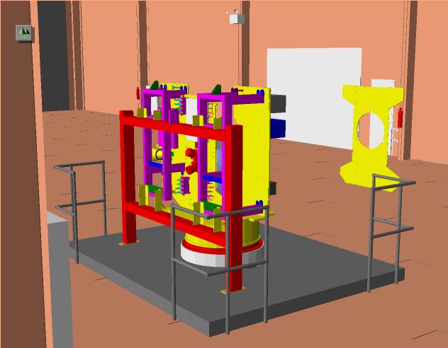
 This picture
is a view of the assembly dolly in the SSB high bay.
It corresponds to the assembly process around 1998 March. One
can see the support frame (red) to which are connected both of the
strongbacks (magenta). The +y-panel is the more heavily populated
panel on the right. The -y-panel is on the left. The propulsion
tank hovers above the +x-panel and next to the -z-panel. The
+z-panel hovers in space off to the left. The brown cylindrical
parts on the -z-panel are the inertial measurement units (IMUs).
Just below and to the left is the navigation camera. The brown box
on the +x-panel is the solar array switching unit SASU.
All of the visible components on the +y-panel are telecommunications
components.
This picture
is a view of the assembly dolly in the SSB high bay.
It corresponds to the assembly process around 1998 March. One
can see the support frame (red) to which are connected both of the
strongbacks (magenta). The +y-panel is the more heavily populated
panel on the right. The -y-panel is on the left. The propulsion
tank hovers above the +x-panel and next to the -z-panel. The
+z-panel hovers in space off to the left. The brown cylindrical
parts on the -z-panel are the inertial measurement units (IMUs).
Just below and to the left is the navigation camera. The brown box
on the +x-panel is the solar array switching unit SASU.
All of the visible components on the +y-panel are telecommunications
components.
 The medium-gain antenna (MGA) peeks out from behind the +y-panel.
The gray box on the -y-panel is the electronics box for the dust flux monitor
(DFM). The blue box is the power box (PCA), and the gray box above it is the
command and data handling (C&DH) box, which is the flight computer and
associated hardware.
The medium-gain antenna (MGA) peeks out from behind the +y-panel.
The gray box on the -y-panel is the electronics box for the dust flux monitor
(DFM). The blue box is the power box (PCA), and the gray box above it is the
command and data handling (C&DH) box, which is the flight computer and
associated hardware.
The picture on the right shows the same model as in the previous image, but
from the opposite side. The star camera (red), reaction engine modules
(REMs) and a thermal-control louvre are now visible on the -z-panel.
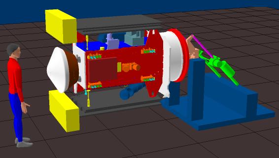 The fully configured spacecraft in a
horizontal position is shown here on the left. The spacecraft is attached to
the rotation fixture. Above the -z-panel can be seen the navigation camera
(purplish) and, to the right, the navigation camera's periscope (blue-gray).
Behind those two components is an enclosure that houses the battery. The
cometary and interstellar dust analyzer (CIDA) pokes out from underneath the
-z-panel. The sample return capsule (SRC) is visible on the left. The solar
panels are obviously folded, and the solar panel Whipple shields are facing
opposite from the cruise direction. The fully configured spacecraft in a
horizontal position is shown here on the left. The spacecraft is attached to
the rotation fixture. Above the -z-panel can be seen the navigation camera
(purplish) and, to the right, the navigation camera's periscope (blue-gray).
Behind those two components is an enclosure that houses the battery. The
cometary and interstellar dust analyzer (CIDA) pokes out from underneath the
-z-panel. The sample return capsule (SRC) is visible on the left. The solar
panels are obviously folded, and the solar panel Whipple shields are facing
opposite from the cruise direction.
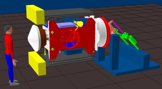 This shows the +z-panel with its
conspicuous high-gain
antenna (HGA). Above the +z-panel are the MGA (yellow) and a thermal
control louvre (purplish). The waveguide that feeds the HGA is the
yellow arm with an elbow. The two bright dots at the left end of the
+z-panel are the sun sensors. This shows the +z-panel with its
conspicuous high-gain
antenna (HGA). Above the +z-panel are the MGA (yellow) and a thermal
control louvre (purplish). The waveguide that feeds the HGA is the
yellow arm with an elbow. The two bright dots at the left end of the
+z-panel are the sun sensors.
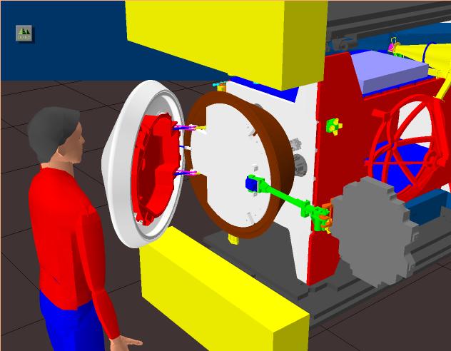 To the right is a view looking inside of the opened SRC. The
aerogel grid (gray) is deployed at the end of its (green) deployment
arm. The aerogel canister lid is colored red.
To the right is a view looking inside of the opened SRC. The
aerogel grid (gray) is deployed at the end of its (green) deployment
arm. The aerogel canister lid is colored red.
Below is a final view of the spacecraft in its vertical
(launch) configuration. The yellow plate above the (orange) star
camera is the navigation camera's radiator.

Data and images provided by Tom Vaughan, Lockheed Martin Astronautics,
Denver, Colorado.
|