|
|||||||||||
 |
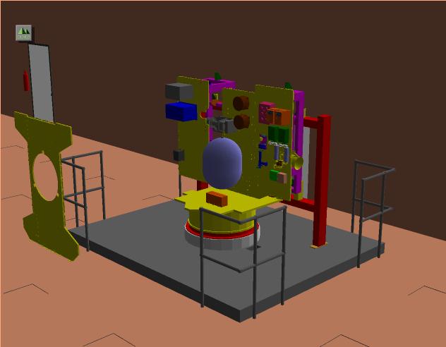
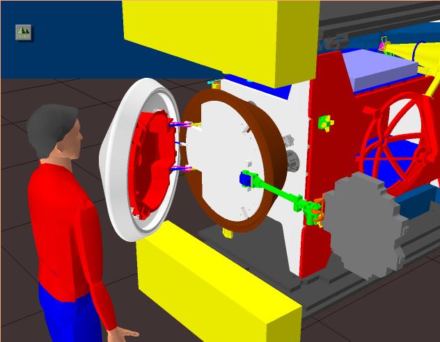
Spacecraft Assembly in a Virtual Prototyping FacilityThe Virtual Prototype Facility is a software tool used to simulate the assembly process of the Stardust spacecraft. Each of the components can be added in any order desired to see if there is a conflict in the way they fit together and operate.
Bright colors are used to help distinguish one part from another. From
this virtual design, the plans for the actual assembly process can be
verified. This versatile software allows viewing the spacecraft
assembly from any angle, making it easy to check each aspect of the
design. It also aids in determining if there are problems of access
that would make it difficult for the spacecraft engineers to perform
certain tasks. Taking this maintenance-conscious engineering approach
is essential in the planning phase of design, as it makes certain the
technicians can make adjustments to any area of the spacecraft.
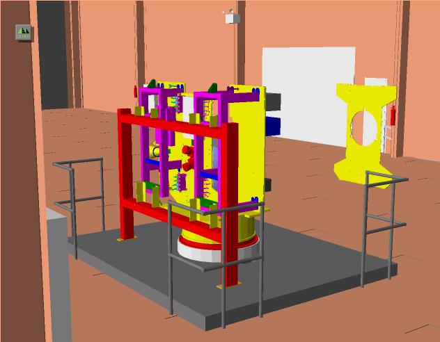
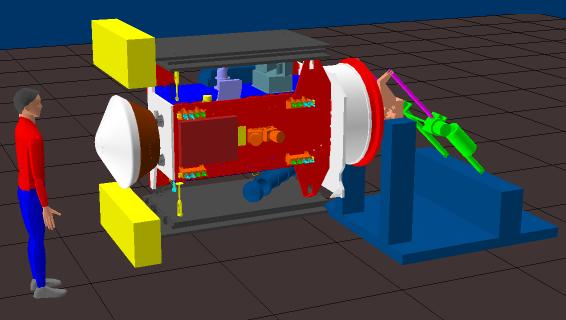
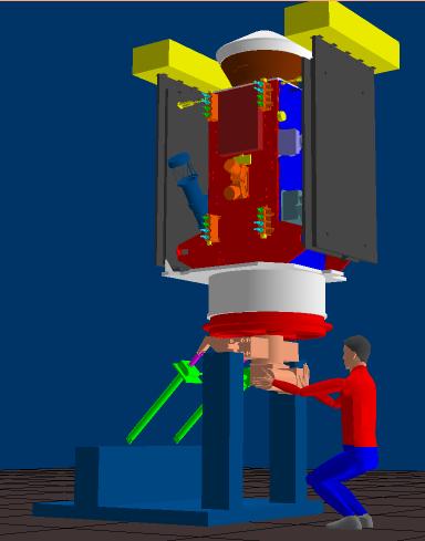
This is a view of the assembly dolly in the SSB high bay. It corresponds to the Stardust spacecraft assembly process around 1998 March. Notice the support frame (red) that is connected to both of the "strong backs" (magenta). The +y-panel is the more heavily populated panel on the right. The -y-panel is on the left. The propulsion tank hovers above the +x-panel and next to the -z-panel. The +z-panel hovers in space off to the left. The brown cylindrical parts on the -z-panel are the inertial measurement units (IMUs). Just below and to the left is the navigation camera. The brown box on the +x-panel is the solar array switching unit SASU. All of the visible components on the +y-panel are telecommunications components. The medium-gain antenna (MGA) peeks out from behind the +y-panel. The gray box on the -y-panel is the electronics box for the dust flux monitor (DFM). The blue box is the power box (PCA), and the gray box above it is the command and data handling (C&DH) box, which is the flight computer and associated hardware.
Behind those two components is an enclosure that houses the battery. The cometary and interstellar dust analyzer (CIDA) pokes out from underneath the -z-panel. The sample return capsule (SRC) is visible on the left. The solar panels are folded, and the solar panel Whipple shields face opposite from the cruise direction.
|
||||||||||
 |
|||||||||||
 |
|||||||||||
|
|||||||||||