


Stardust / Stardust NExT
Type
Launch
Target
Objective
What was Stardust / Stardust NExT?
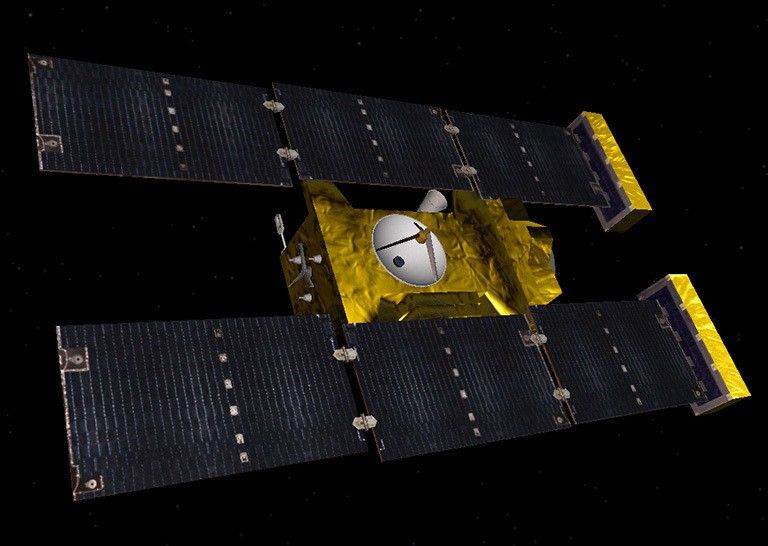
NASA's Stardust was the first spacecraft to bring samples from a comet to Earth, and the first NASA mission to return particles from beyond the Earth Moon orbit.
| Nation | United States of America (USA) |
| Objective(s) | Comet Sample Return, Comet and Asteroid Flybys |
| Spacecraft | Stardust |
| Spacecraft Mass | 849 pounds (385 kilograms) |
| Mission Design and Management | NASA / Jet Propulsion Laboratory |
| Launch Vehicle | Delta 7426-9.5 (no. D266) |
| Launch Date and Time | Feb. 7, 1999 / 21:04:15 UT |
| Launch Site | Cape Canaveral, Fla. / Launch Complex 17A |
| Scientific Instruments | 1. Dust Flux Monitor Instrument (DFMI) 2. Cometary and Interstellar Dust Analyzer (CIDA) 3. Navigation Camera (NC) 4. Stardust Sample Collection (SSC) 5. Dynamic Science Experiment (DSE) |
Firsts
- Stardust was the first spacecraft to bring samples from a comet to Earth.
Key Dates
Feb. 7, 1999: Launch
Feb. 22 to May 1, 2000: First interstellar dust collection operation was carried out
Jan. 15, 2001: Stardust flew by Earth for a gravity assist
Nov. 2, 2002: Stardust flew by asteroid 5535 Annefrank
Jan. 2, 2004: Closest encounter with Comet Wild 2 (or 81P/Wild)
Jan. 15, 2006: Stardust’s Sample Return Capsule (SRC) returns to Earth
July 2007: NASA approved extended mission known as New Exploration of Tempel 1 (NExT)
Feb. 15, 2011: Stardust/NExT flew by comet Tempel 1
March 24, 2011: The spacecraft carried out a final engine and sent its last transmission ending the mission
In Depth: Stardust / Stardust NExT
Stardust was the fourth of NASA’s Discovery Program of low-cost exploration missions (after NEAR, Mars Pathfinder, and Lunar Prospector), and the first American mission dedicated solely to studying a comet. It was also the second robotic mission (after Genesis) designed to bring extraterrestrial material from beyond lunar orbit back to Earth.
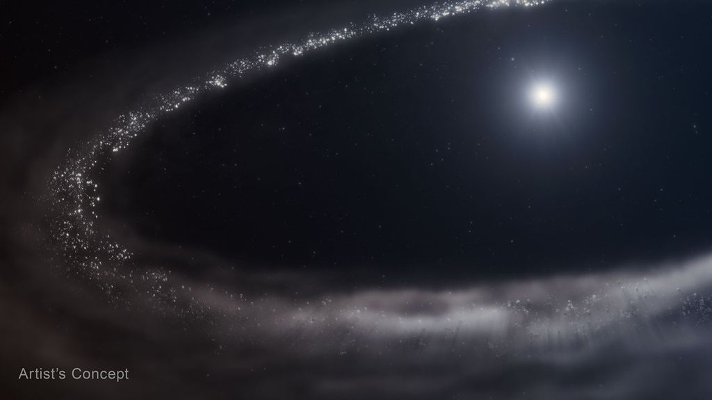
Its primary goal was to fly by the Comet Wild 2 (pronounced “Vilt 2”), collect samples of dust from the coma of the comet as well as additional interstellar particles, and then bring the samples to Earth.
Stardust was comprised of a 560-pound (254-kilogram) spacecraft that included a 100-pound (45.7-kilogram) sample return capsule shaped like a blunt-nosed cone. The spacecraft had five major components: a heat shield, backshell, sample canister, parachute system and avionics.
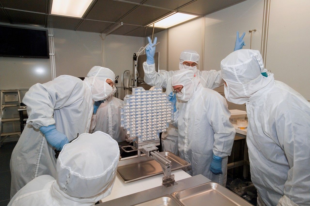
The samples were to be collected using a low-density microporous silica-based substance known as aerogel, attached to panels on the spacecraft to “soft-catch” and preserve the cometary materials.
The spacecraft was launched into a heliocentric orbit that would bring it around the Sun and past Earth for a gravity-assist maneuver to direct it to Wild 2 after a flyby of the minor planet Annefrank in November 2002.
After midcourse corrections Dec. 28, 1999, and Jan. 18, Jan. 20 and Jan. 22, 2000, its first interstellar dust collection operation was carried out between Feb. 22 and May 1, 2000.
After approximately a year in heliocentric orbit, Stardust flew by Earth (at a range of about 3730 miles or 6,008 kilometers) Jan. 15, 2001, for a gravity assist to send it on a second sample collection exercise between July and December 2002.
On Nov. 2, 2002, at 04:50 UT, Stardust flew by asteroid 5535 Annefrank at a range of about 1,900 miles (3,078 kilometers). During the encounter, the spacecraft’s dust collectors collected samples while its camera returned 72 images.
More than a year later, on Dec. 31, 2003, the spacecraft entered the coma of Comet Wild 2 (or 81P/Wild) with the closest encounter (at a range of 155 miles or 250 kilometers) taking place at 19:22 UT Jan. 2, 2004.
The sample collector, which had been deployed Dec. 24, 2003, was retracted about six hours after closest approach, stowed, and then sealed in the sample vault. The imaging system took 72 images of the comet’s nucleus.
Exactly as planned, after a 2.9 billion-mile (4.63 billion-kilometer) trip lasting more than two years, at 05:57 UT Jan. 15, 2006, Stardust’s Sample Return Capsule (SRC) separated from the main vehicle and four hours later, it entered Earth’s atmosphere.
Slowed down by the drogue and main parachutes, the capsule landed at 10:10 UT within a 19 x 52-mile (30 × 84-kilometer) landing zone at the U.S. Air Force Test and Training Range in Utah. Because of high winds, the capsule drifted north of the ground track, but fortunately, a locator beacon allowed recovery teams to find the capsule 44 minutes after landing.
The capsule had returned more than 10,000 particles larger than 1 micrometer from Wild 2.
Meanwhile, the main spacecraft was diverted so it wouldn't re-enter Earth’s atmosphere. At 06:13 UT Jan. 15, Stardust fired its engines, flew past Earth and then the Moon before entering hibernation mode on Jan. 29.
In July 2007, NASA approved an extended mission for Stardust known as New Exploration of Tempel 1 (NExT) that envisaged a flyby of Comet Tempel 1 (or 9P/Tempel), which had been a target for the 2005 Deep Impact mission. (On July 3, 2005, Deep Impact released an impactor probe, which, using small thrusters, hit the comet July 4, 2005, creating a crater estimated to be about 490 feet or 150 meters in diameter).
Stardust, now known as Stardust/NExT, flew by Tempel 1 at 04:42:00 UT Feb. 15, 2011, at a range of 112 miles (181 kilometers), returning 72 images of the nucleus. This was the first time a comet had been revisited. It was also during this flyby that investigators were able to conclusively identify the crater caused by the Deep Impact mission’s probe.
Stardust carried out a final engine burn on March 24, 2011, exhausting all of its propellant. It sent its last transmission at 12:33 UT the same day, ending an 11-year mission.
The analysis of the samples returned by the spacecraft showed the presence of a wide range of organic compounds. In August 2014, NASA announced that seven rare, microscopic interstellar dust particles dating from the very origins of the solar system were among the samples collected by Stardust.
Key Resources
Siddiqi, Asif A. Beyond Earth: A Chronicle of Deep Space Exploration, 1958-2016. NASA History Program Office, 2018.