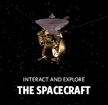
Cassini

RADAR Engineering Technical Write-up
Team Lead: Dr. Charles Elachi
RADAR General Description:
The Cassini Radar (RADAR) uses the five-beam Ku-band antenna feed assembly associated with the spacecraft high gain antenna to direct radar transmissions toward targets, and to capture blackbody radiation and reflected radar signals from targets.
RADAR Scientific Objectives:
- To determine whether oceans exist on Titan, and, if so, to determine their distribution.
- To investigate the geologic features and topography of the solid surface of Titan.
- To acquire data on non-Titan targets (rings, icy satellites) as conditions permit.
RADAR Sensing Instruments:
- Synthetic Aperture Radar Imager [SAR] (13.78 GHz Ku-band; 0.35 to 1.7 km resolution)
- Altimeter (13.78 GHz Ku-band; 24 to 27 km horizontal, 90 to 150 m vertical resolution)
- Radiometer (13.78 GHz passive Ku-band; 7 to 310 km resolution)
RADAR Instrument Characteristics:
- Mass (current best estimate) = 41.43 kg
- Peak Operating Power (current best estimate) = 108.40 W
- Peak Data Rate (current best estimate) = 364.800 kilobits/sec
The Cassini Radar (RADAR) will be used to investigate the surface of Saturn's moon Titan by taking four types of observations: imaging, altimetry, backscatter, and radiometry. In the imaging mode of operation, the RADAR instrument will bounce pulses of microwave energy off the surface of Titan from different incidence angles and record the time it takes the pulses to return to the spacecraft. These measurements, when converted to distances (by dividing by the speed of light), will allow the construction of visual images of the target surface. Radar will be used to image Titan because the moon's surface is hidden from optical view by a thick, cloud-infested atmosphere: radar can "see" through such cloud cover.
Radar altimetry similarly involves bouncing microwave pulses off the surface of the target body and measuring the time it takes the "echo" to return to the spacecraft. In this case, however, the goal will not be to create visual images but rather to obtain numerical data on the precise altitude of the surface features of Titan. In the backscatter mode of operation, the RADAR will act as a scatterometer. That is, it will bounce pulses off Titan's surface and then measure the intensity of the energy returning. This returning energy or backscatter, is always less than the original pulse, because surface features inevitably reflect the pulse in more than one direction. From the backscatter measurements, scientists can infer the composition of the surface of Titan.
Finally, in the radiometry mode, the RADAR will operate as a passive instrument, simply recording the energy emanating from the surface of Titan. This information will tell scientists the amount of latent heat (i.e.. moisture) in the moon's atmosphere, a factor that has an impact on the precision of the other measurements taken by the instrument. During imaging, altimetry, and backscatter operations, the RADAR instrument will transmit linear frequency-modulated Ku-band pulsed signals toward the surface of Titan using the high-gain antenna (HGA). These signals, after reflection from the surface, will be captured by the same antenna and detected by the RADAR Radio Frequency Electronics Subsystem. During radiometry operations, the instrument will not transmit any radar signals, but the HGA will again be used for radiometric observations.
To improve the surface coverage by radar imaging, a switched, multiple Ku-band antenna feed array structure is part of the HGA and permits the formation of five antenna beam patterns. Each of these beams will have a different pointing angle relative to the antenna reflector's focal axis.
The major functional components of the RADAR Subsystem are:
For information on these components, click on their names.
The Radio Frequency Electronics Subsystem (RFES) has three principal functions: the transmission of high-power frequency-modulated and unmodulated pulses, the reception of both reflected energy from the target and passive radiometric data, and the routing of calibration signals. The RFES has a fully enclosed structural housing and Faraday cage (i.e., an electrostatic shield). The RFES electronics units are individually enclosed and are mounted to the RFES housing wall opposite the wall that mounts to the spacecraft. For thermal control, heat flows conductively from the units to the housing wall and is then radiated away from the RFES.
The RFES consists of the following components:
The frequency generator (FG) contains an ultra-stable oscillator that is the system timing source for the RADAR instrument.
The digital chirp generator (DCG) generates the low-power, baseband frequency, modulated pulse upon request from the RADAR Digital Subsystem. Both the bandwidth and the pulse width of this pulse can be varied in accordance with the parameters received from the Digital Subsystem.
The chirp up-converter and amplifier (CUCA) converts the baseband chirp pulse to Ku band and provides the up-converted pulse to the high-power amplifier.
The high-power amplifier (HPA) receives a low-power Ku-band chirp pulse from the CUCA and amplifies that pulse to the required power level for transmission.
The purpose of the front-end electronics (FEE) is to route the high-power transmission pulses, the returning low-energy echoes and radiometric signals, and the calibration signals. The FEE receives the high-power pulse from the HPA and routes the signal to one of five different antenna ports on the RFES via an antenna switch module. The echo returns and radiometric signals are routed from one of the five antenna ports to the RFES microwave receiver. The FEE also steers the selected calibration signal to the microwave receiver during periods of calibration mode operation.
The microwave receiver (MR) receives signals at Ku band and down-converts these to baseband so that they can be properly sampled. The sources of these signals are the echo returns, radiometric signals, and calibration signals routed through the FEE. The MR receives the re-routed chirp calibration signal from the CUCA and passes that signal to the FEE for proper routing. The MR is also the source of the noise diode calibration signal that is provided to the FEE for routing. MR gain and bandwidth information is provided to the MR from the DSS.
The RFES power supply converts the (approximately) 30-volt d.c. input from the Power and Pyrotechnic Subsystem to the required voltages for the RFES.
The RADAR Digital Subsystem (DSS) performs three principal functions: reception and depacketization of RADAR commands from the Command and Data Subsystem (CDS), configuration control and timing signal generation for RADAR, and the packetization of RADAR housekeeping (i.e., hardware status) data and science data for transfer to the CDS.
DSS subassemblies are contained within a spacecraft bay and will be supported in shear by shear plates and the top and bottom rings of the Cassini spacecraft bus. Electronic harnesses, which face inboard on the spacecraft and be supported by the inboard shear plate, are used to provide interconnections between the RADAR subassemblies and the spacecraft.
The DSS uses two primary modes of heat transfer in its design. These are (1) the conduction of heat from the electronic components to the subchassis and the outboard shear plate, and (2) the radiation of heat from the outboard shear plate to the space environment. High-power heat dissipation components are mounted on a special heatsink bracket, which is bolted directly to the outboard shear plate to optimize heat transfer. Thermal compounds were applied between the components and the heatsink to minimize contact thermal resistance.
The DSS consists of the following components:
For information on these components, click on their names.
The bus interface unit (BUI) is the interface between RADAR and the CDS. On the RADAR side, the BIU interfaces to the flight computer unit for command, software, and data transfers.
The flight computer unit (FCU) receives commands and software from the CDS and sends data and status to CDS by way of the BIU. It depacketizes the commands and provides the RADAR configuration and timing information to the control and timing unit. It also receives housekeeping values in a predetermined order from the low-speed A/D converter and packetizes the housekeeping and science data to be passed to the CDS by way of the BIU. In addition, the FCU receives spacecraft time broadcasts and RADAR software uploads from CDS by way of the BIU. The FCU is built around an engineering flight computer (EFC) with additional banks of ROM and internal interface circuitry.
The purpose of the control and timing unit (CTU) is to control the hardware configuration and the timing of control signals within RADAR. The parameters for determining RADAR configuration and timing are passed to the CTU from the FCU. The CTU provides the configuration and timing control signals to the RFES and to other portions of the DSS. In addition, the CTU is responsible for updating to millisecond resolution the spacecraft time received from the CDS.
The signal conditioner unit (SCU) consists of a science data buffer and high- and low-speed analog-to-digital (A/D) converters. The science data buffer (SDB) is the digital data rate buffer for RADAR. The sole purpose of the SDB is to receive and store the high-rate digital science data from the high-speed A/D converter during the proper receive window period (as determined by the CTU) and then to provide this data upon request to the FCU at a slower rate. The high-speed A/D converter digitizes the imaging data output from the RFES microwave receiver and provides the data to the SDB for buffering. The low-speed A/D converter performs two tasks. It digitizes the analog housekeeping telemetry values from throughout RADAR at predetermined times and provides these digitized values to the FCU upon request. It also digitizes the radiometer output from the RFES microwave receiver and provides those values to the FCU upon request.
The DSS power supply converts the (approximately) 30-volt d.c. input from the Power and Pyrotechnic Subsystem to the voltages required for the DSS.
The RADAR Energy Storage Subsystem (ESS) converts the (approximately) 30-volt d.c. input from the PPS to a higher voltage, stores energy in a capacitor bank, and provides a regulated voltage to the high-power amplifier (HPA) of the RFES. The ESS subassemblies are contained within a spacecraft bay and are supported in shear by shear plates and the top and bottom rings of the Cassini spacecraft bus. High-strength fasteners will be used to tie the electronics assemblies to the spacecraft. Electronic harnesses, which face inboard on the spacecraft and be supported by the inboard shear plate, are used to provide interconnections between the RADAR subassemblies and the spacecraft.
The ESS uses two primary modes of heat transfer in its design. These are (1) the conduction of heat from the electronic components to the subchassis and the outboard shear plate, and (2) the radiation of heat from the outboard shear plate to the space environment. High-power heat dissipation components will be mounted on a special heatsink bracket, which will be bolted directly to the outboard shear plate to optimize heat transfer. Thermal compounds will be applied between the components and the heatsink to minimize contact thermal resistance.
The ESS consists of:
For information on these components, click on their names.
The boost circuitry increases the (approximately) 30-volt d.c. input power to approximately 85 volts d.c. for more efficient energy storage by the capacitor bank. Soft-start circuitry limits the current draw from the power source, and an input voltage filter prevents electromagnetic interference (EMI) from being conducted back into the source.
The capacitor bank stores energy to supply to the buck regulator (and the HPA) during RADAR pulse bursts. The capacitor bank voltage drops during each burst but returns to normal before the next burst.
The buck regulator regulates the varying capacitor bank voltage for the HPA.
Cassini Orbiter Instruments
They surveyed and sniffed, analyzed and scrutinized. They took stunning images in various visible spectra. Cassini's 12 science instruments were designed to carry out sophisticated scientific studies of Saturn, from collecting data in multiple regions of the electromagnetic spectrum, to studying dust particles, to characterizing Saturn's plasma environment and magnetosphere.
Optical Remote Sensing
Mounted on the remote sensing pallet, these instruments studied Saturn and its rings and moons in the electromagnetic spectrum.
Fields, Particles and Waves
These instruments studied the dust, plasma and magnetic fields around Saturn. While most didn't produce actual "pictures," the information they collected is critical to scientists' understanding of this rich environment.
Microwave Remote Sensing
Using radio waves, these instruments mapped atmospheres, determined the mass of moons, collected data on ring particle size, and unveiled the surface of Titan.