


Magellan
Type
Launch
Target
Objective
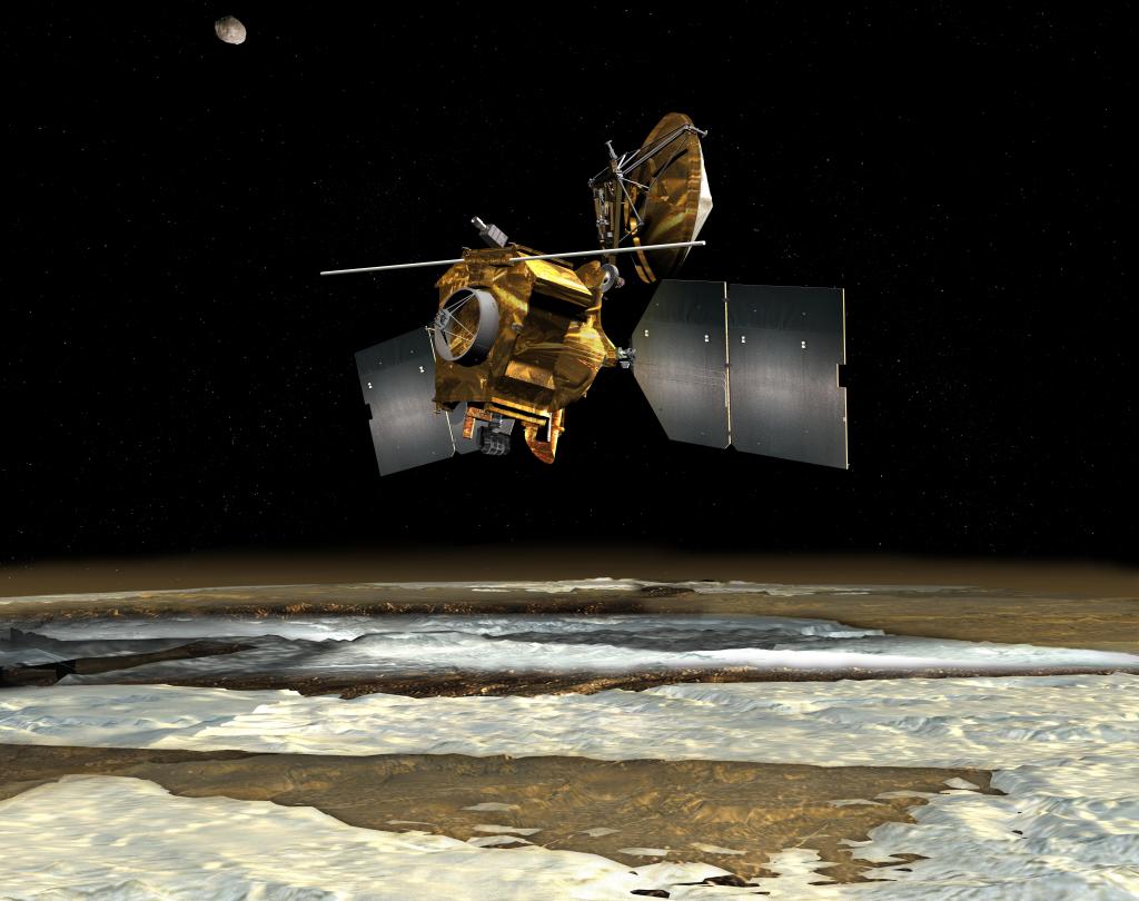
What was Magellan?
NASA's Magellan mission to Venus was one of the most successful deep space missions. It was the first spacecraft to image the entire surface of Venus and made several discoveries about the planet. Magellan burned up about 10 hours after being commanded to plunge into the Venusian atmosphere.
| Nation | United States of America (USA) |
| Objective(s) | Venus Orbit |
| Spacecraft: | Magellan |
| Spacecraft Mass | 7,595 pounds (3,445 kilograms) |
| Mission Design and Management | NASA / Jet Propulsion Laboratory (JPL) |
| Launch Vehicle | Space Shuttle Atlantis (STS-30R) |
| Launch Date and Time | May 4, 1989 / 18:47:00 UT |
| Launch Site | Kennedy Space Center, Fla. / Launch Complex 39B |
| Scientific Instruments | Synthetic Aperture Radar (RDRS) |
Firsts
- First deep space probe launched by a space shuttle
- First spacecraft to image the entire surface of Venus
Key Dates
May 4, 1989: Launch
May 5, 1989: Deployed from cargo bay of Space Shuttle Atlantis
Aug. 10, 1990: Arrived in Venus orbit
Oct. 13, 1994: Contact lost after Magellan was commanded to plunge into the atmosphere of Venus
In Depth: Magellan
Magellan, named after the Portuguese explorer Ferdinand Magellan (1480-1521), was the first deep space probe launched by the United States in almost 11 years, and also the first probe launched by a space shuttle.
The Challenger disaster in January 1986 profoundly impacted the shuttle launch manifest into the 1990s, which included a number of planetary missions. Magellan, for example, was delayed by at least a year.
Magellan was designed to use a Synthetic Aperture Radar (SAR) to map 70% of the Venusian surface down to a resolution of 390 to 985 feet (120 to 300 meters).
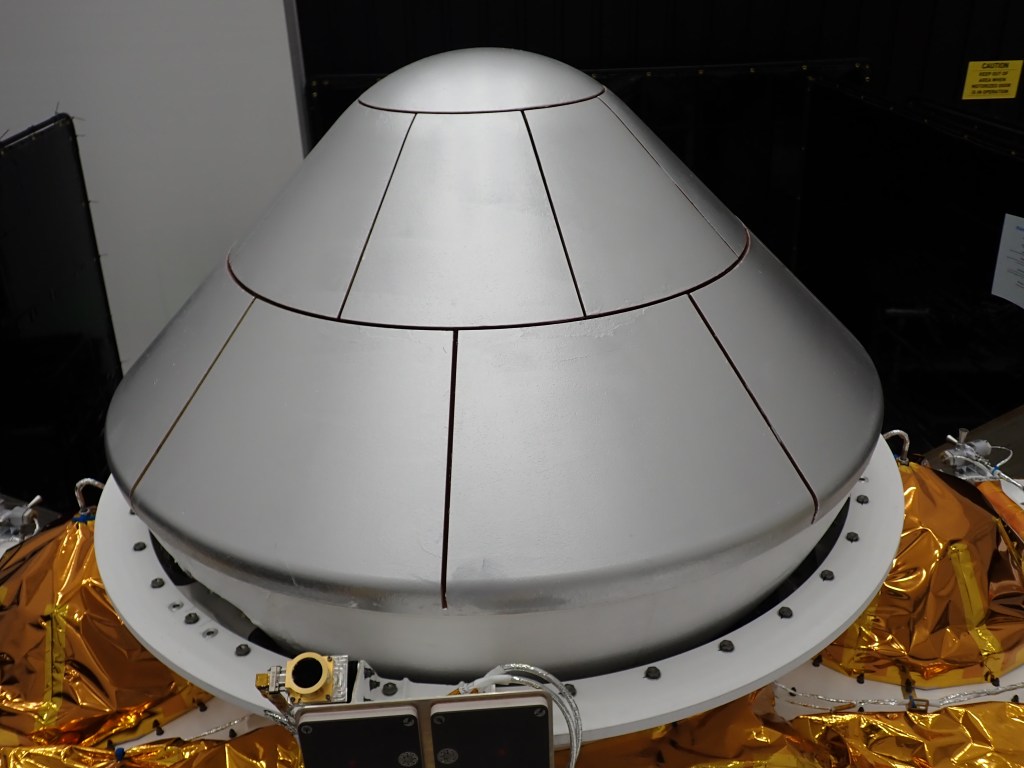
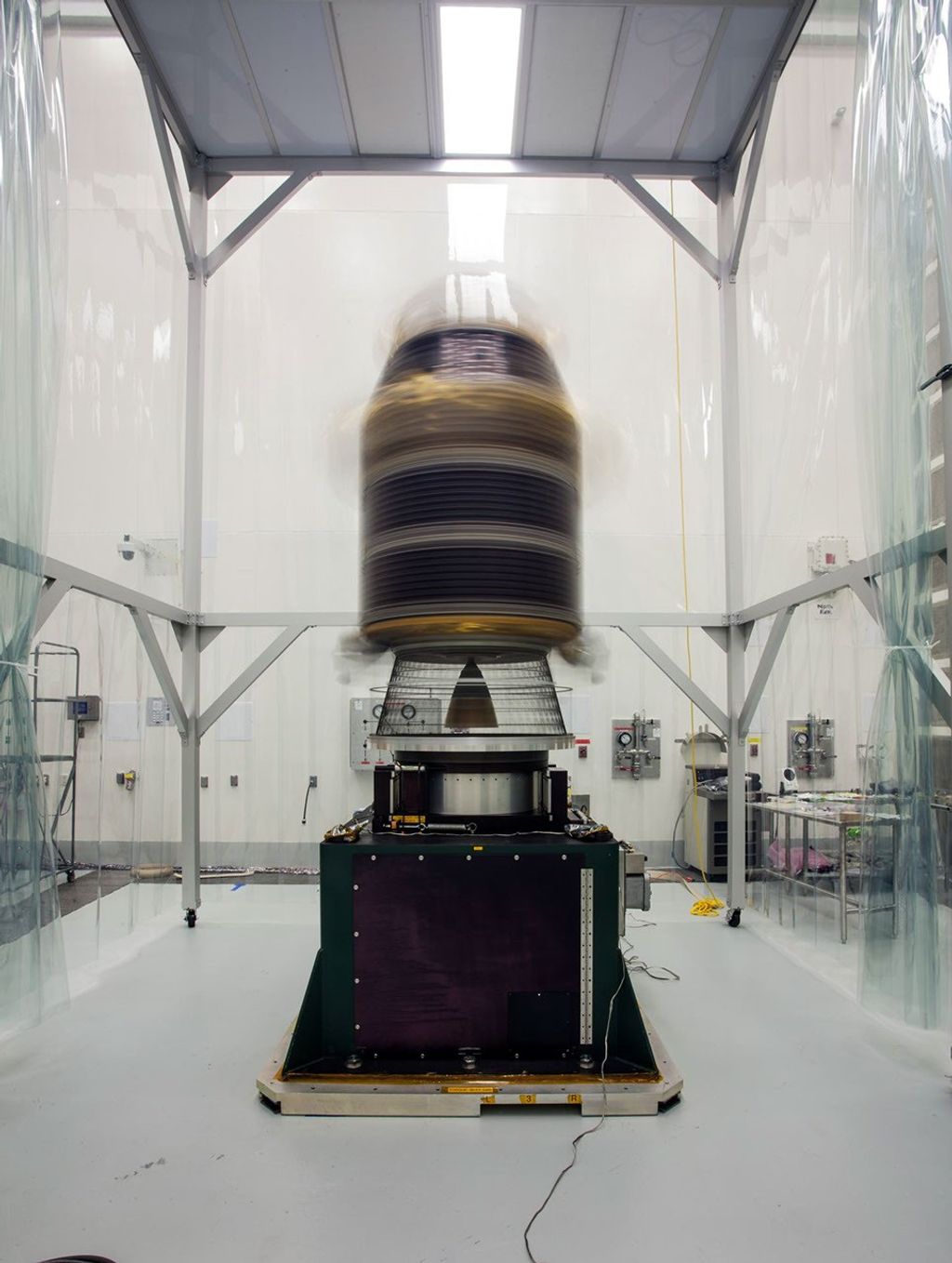
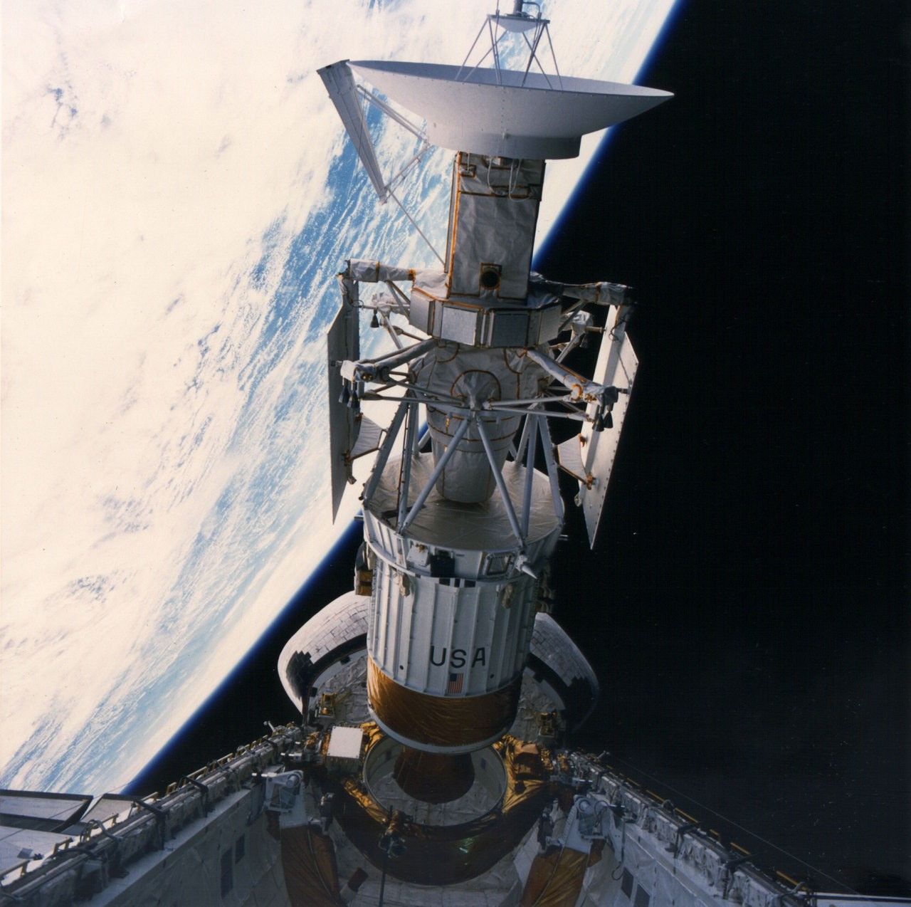
The basic bus was assembled using spare parts left over from various prior missions including Voyager, Galileo, Ulysses, and Mariner 9. Magellan was deployed by the STS-30R crew and released at 01:01 UT May 5, 1989, from the payload bay of the Space Shuttle Atlantis. One hour later, a two-stage Inertial Upper Stage (IUS) fired to send the spacecraft on a trajectory to rendezvous with Venus.
After three en route trajectory corrections (May 21, 1989, March 13, 1990, and July 25, 1990), Magellan arrived in Venus orbit on Aug. 10, 1990. Orbital parameters were 185 x 5,260 miles (297 × 8,463 kilometers) at 85.5 degrees inclination.
Six days after entering orbit, Magellan suffered a communications outage lasting 15 hours. After a second 17 hour-interruption on Aug. 21, 1990, the ground sent up new preventative software to reset the system in case of such anomalies.
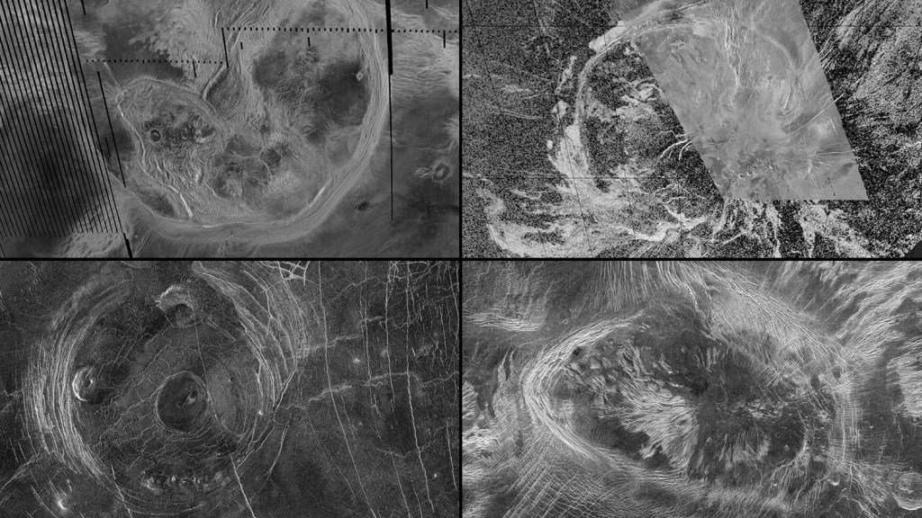
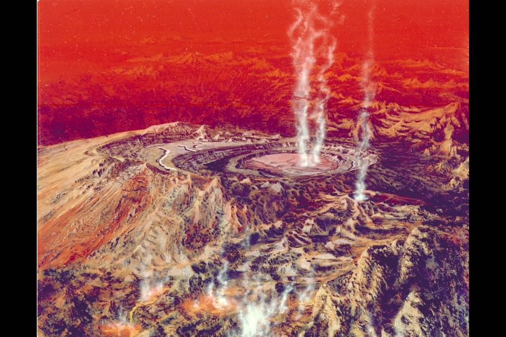
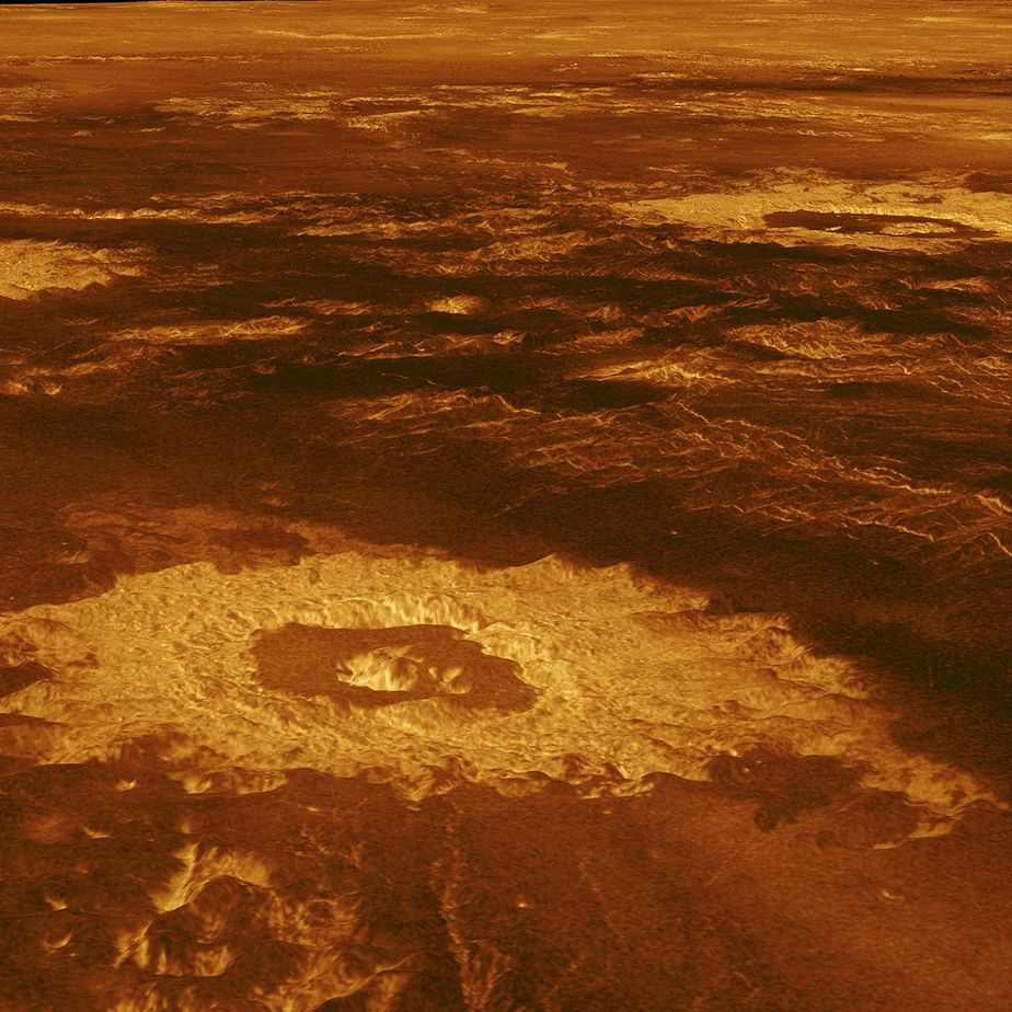
Beginning Sept. 15, 1990, the spacecraft began returning high-quality radar images of the Venusian terrain that showed evidence of volcanism, tectonic movement, turbulent surface winds, miles (kilometers) of lava channels, and pancake-shaped domes.
Magellan completed its first 243-day cycle (i.e., the time it took for Venus to rotate once under Magellan’s orbit) of radar mapping on May 15, 1991, providing the first clear views of 83.7% of the surface.
The spacecraft returned 1,200 gigabits of data, far exceeding the 900 gigabits of data from all NASA planetary missions combined at the time.
The spacecraft’s second mapping cycle, already beyond the original goals of the mission, ended on Jan. 15, 1992, raising coverage to 96%. A third cycle that focused on stereo imaging ended on Sept. 13, 1992, finished coverage at 98%.
Additional mapping cycles were conducted: a fourth ended May 23, 1993; a fifth Aug. 29, 1994, and a sixth Oct. 13, 1994. These cycles focused on obtaining gravimetric data on the planet.
In the summer of 1993, controllers commanded the spacecraft to drop into the outermost regions of the Venusian atmosphere and then successfully used an aerobraking method to circularize its orbit. Contact was lost after 10:05 UT Oct. 13, 1994, as the spacecraft was commanded to plunge into the atmosphere to gather aerodynamic data. The spacecraft burned up in the Venusian atmosphere about 10 hours later after one of the most successful deep space missions.
Magellan found that at least 85% of the Venusian surface is covered with volcanic flows. The spacecraft’s data suggested that despite the high surface temperatures (887 degrees Fahrenheit or 475 degrees Celsius) and high atmospheric pressures (92 atmospheres), the complete lack of water makes erosion an extremely slow process on the planet. As a result, surface features can persist for hundreds of millions of years.
In addition, the spacecraft found that such phenomena as continental drift are not evident on the planet. Its imagery contributed to the best high-resolution radar maps of Venus’ surface to date, improving on the images returned by the Soviet Venera 15 and 16 in the 1980s.
Key Resources
Siddiqi, Asif A. Beyond Earth: A Chronicle of Deep Space Exploration, 1958-2016. NASA History Program Office, 2018.
Legacy Magellan Mission Website
Mission Archives: STS-30 | Space Shuttle Atlantis-Magellan Mission