Deep Space Network
- All the DSSs at the GDSCC in California are designated with numbers in the teens and twenties: DSS13, DSS14, DSS15, DSS24, DSS25, DSS26, etc.
- All the DSSs at the CDSCC in Australia are designated with numbers in the thirties and forties: DSS34, DSS43, DSS45 and DSS46.
- All the DSSs at the MDSCC in Spain are designated with numbers in the fifties and sixties: DSS54, DSS55, DSS65, and DSS63.
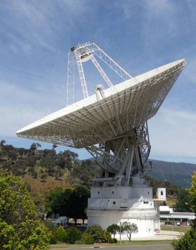
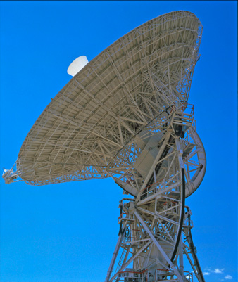
The three 70 m DSSs were originally built as 64 m diameter antennas. The first, GDSCC's DSS-14, also known as the Mars Station for its support of Mariner-4, began operation in 1966. All three were expanded to 70 m diameter from 1982 to 1988 to increase their sensitivity to support Voyager 2's encounter with Neptune.
The 70 m DSSs are used for deep-space mission support, radio astronomy, and VLBI. The 70 m DSS14 at GDSCC is also used for radar astronomy, which is known as Goldstone Solar System Radar, GSSR.
The 70 m subnet DSSs support both X-band and S-band uplink and downlink.
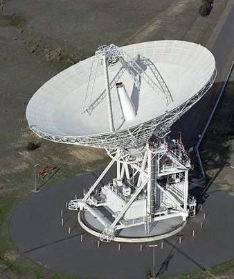
HEF stands for High-Efficiency. This subnet was installed to replace the older 34 m Standard, STD, subnet. The 34 m STD subnet DSSs had a polar-axis, or HA-DEC, design and were originally built with 26 m diameter reflectors and later upgraded to 34 m.
The upgrade required repositioning the entire DSS up on concrete footings so that the reflector could point to low elevations without striking the ground. The 34 m STD DSSs at CDSCC (DSS42) and at MDSCC (DSS61) have been dismantled. The GDSCC 34 m STD (DSS12) was converted to an educational resource and renamed the Goldstone-Apple Valley Radio Telescope, GAVRT.
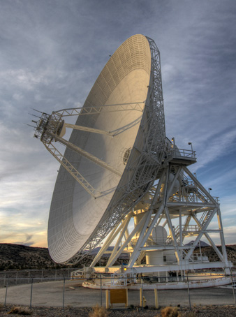
The 34 m HEF subnet was designed with the more efficient azimuth-elevation mounting and a 34 m reflector from the start, with a precision-shaped surface for maximum signal-gathering capability at X-band radio frequencies. The 34 m HEF subnet supports mostly deep space missions, but may occasionally support a mission in high Earth orbit.
The 34 m HEF subnet DSSs support X-band uplink and downlink, and S-band downlink. As of 2017, the 34 m antennas are being decommissioned.
BWG stands for Beam Wave Guide. These, the newest of the DSSs to be designed and implemented, can be recognized by the hole in the middle of their main reflectors where on other DSSs you'd find a feed cone full of microwave equipment.
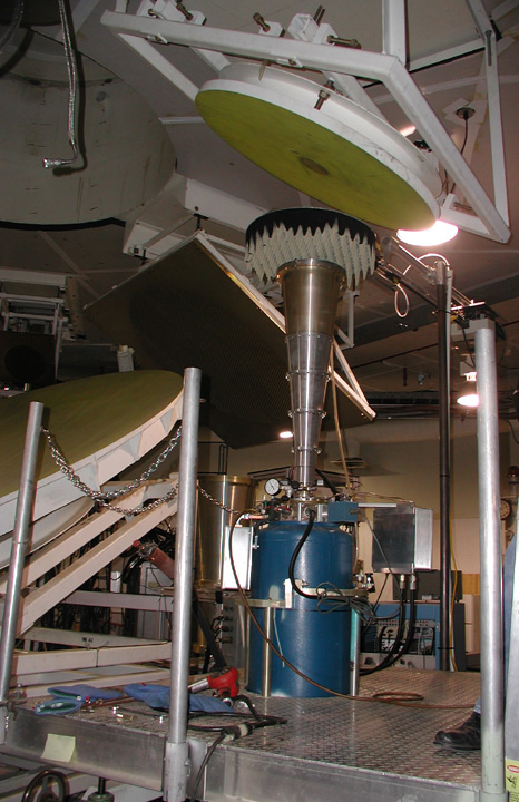
The BWG design does not require sensitive equipment to be mounted in a cramped, moveable feedhorn or room mounted beneath the main reflector, where it is difficult to access for maintenance, repair, and upgrade. Instead, the BWG DSS directs the microwave beam through waveguides via five precision RF mirrors down into a basement room where equipment can be stably mounted on the floor and on balconies, with plenty of room for access.
The image to the right shows two of the beam waveguide reflectors inside the antenna mounting. These two reflectors maintain the microwave beam as the antenna moves around in azimuth. Similar reflectors, located higher up in the structure, permit freedom of movement in elevation.
The 34 m BWG subnet supports mostly deep space missions, but may occasionally support a mission in high Earth orbit.
The 34 m BWG subnet DSSs generally support both X-band and S-band uplink and downlink, although this is not true for all of the BWG DSSs at GDSCC. Some at GDSCC also have Ka-band uplink and downlink capability.
View the fascinating construction process of a new 34 m BWG DSS in Spain.
The 26 m diameter subnet is used for rapidly tracking Earth-orbiting spacecraft. They were originally built to support the Apollo lunar missions between 1967 and 1972.
The XY-mounted 26 m DSSs were originally part of the Spaceflight Tracking and Data Network, STDN, operated by NASA's Goddard Space Flight Center in Greenbelt, Maryland. They were integrated into the DSN in 1985 when it needed them to track spacecraft in highly elliptical Earth orbits.
The 26 m subnet DSSs support S-band uplink and downlink.
A powerful technique for obtaining higher sensitivity in support of distant spacecraft is arraying. Arraying means electronically combining the signals coming in from two or more DSSs, either at the same DSCC, at two different DSCCs, or with a non-DSN radio telescope. This increases the effective aperture, strengthens reception of the spacecraft's weak signal, and permits the spacecraft to be able to downlink data at a higher rate.
Arraying was conducted between DSS43 and the Parkes radio telescope in Australia in support of the 1986 Voyager 2 encounter with Uranus. The 27-antenna Very Large Array in Socorro New Mexico was arrayed with DSS14 in support of Voyager's 1989 encounter with Neptune. Intercontinental arraying was accomplished in support of the Galileo mission at Jupiter.
Arraying four 34 m DSSs can provide the equivalent of one 70 m DSS. As many as eight antennas can be arrayed at a DCSS.
New antennas are added to the DSN, as budget and circumstance permit, to help support the growing demands for communication and navigation, and to help act as a backup in case of any need for extended periods of maintenance or repair for existing DSSs. Recently added antennas are of the 34 m BWG type.
Future plans call for continuing to add 34 m BWG antennas to each DSCC. This was decided after carefully studying the concept of using a large number of 12 m aperture units, that could be arrayed to achieve performance equivalent to the giant 34 m and 70 m DSSs. One paper describing the concept is by Mark S. Gatti, and is titled, "A Phased Array Antenna for Deep Space Communications" (IEEEAC #1606, December 2007).
There have been studies of the concept of having a communications system located in orbit at Mars. Rather than have all spacecraft communicate individually with antennas of the DSN, such a network would help consolidate the communications and navigation tasks at the red planet.
Unfortunately, the first real component of such a network, the Mars Telecommunications Orbiter, was cancelled in July of 2005 due to budget constraints.
The Mars Reconnaissance Orbiter (MRO) spacecraft serves instead as the main relay for data returned by the Mars Science Laboratory (MSL), a highly capable surface rover that landed in August 2012.
