


Chapter 12: Science Instruments
Chapter Objectives
Upon completion of this chapter you will be able to distinguish between remote- and direct-sensing science instruments, state their characteristics, recognize examples of them, and identify how they are classified as active or passive sensors.
Most interplanetary missions are flown to collect science data. The exceptions are spacecraft like Deep Space 1, whose purpose was to demonstrate new technologies and validate them for future use on science missions. On a science mission, though, all the engineering subsystems and components that we've discussed up to this point serve a single purpose. That purpose is to deliver scientific instruments to their destination, to enable them to carry out their observations and experiments, and to return data from the instruments.
Science Payload
There are many different kinds of scientific instruments. They are designed, built, and tested by teams of scientists working at institutions around the world who deliver them to a spacecraft before its launch. Once delivered, they are integrated with the spacecraft, and tests continue with other subsystems to verify their commands function as expected, telemetry flows back from the instrument, and its power, thermal, and mechanical properties are within limits. After launch, the same scientists who created an instrument may operate it in flight through close cooperation with the rest of the flight team.
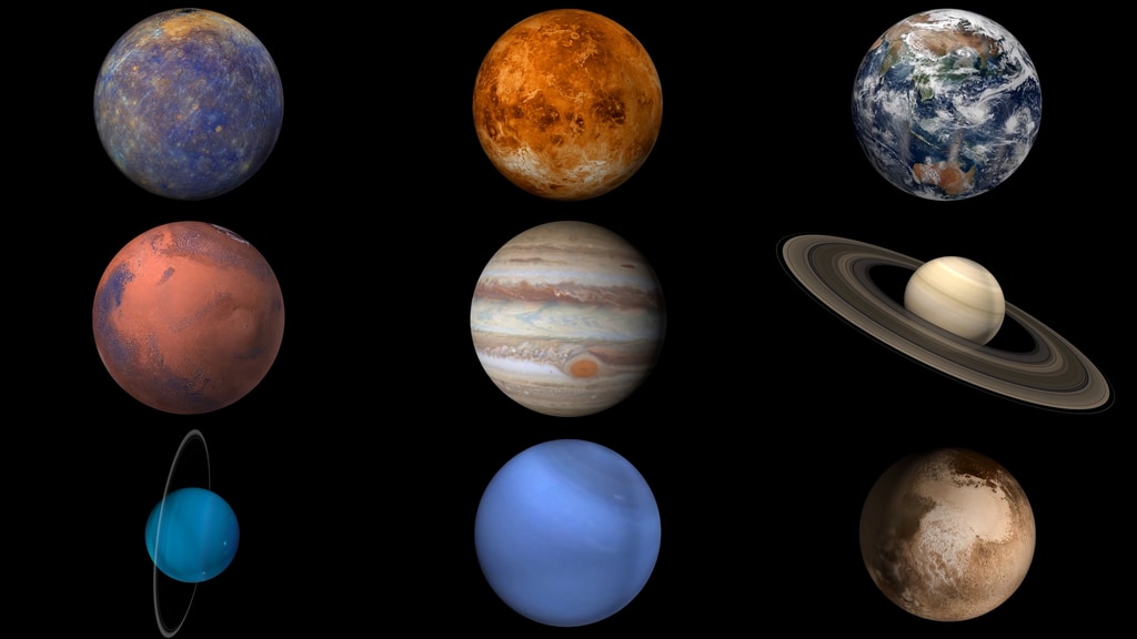
The large illustration (GIF, 63 KB) introduced in Chapter 11 shows some of the science instruments discussed in this chapter.
The purpose of this chapter is not to describe all science instruments. There are too many, they are complicated, and new ones are always being designed. We can, however, describe the basic categories of science instruments, and populate them with some examples. This will provide some keys so you will be able to recognize current and future science instruments, to immediately know their general purpose, to broadly understand how they operate, and to realize what their basic operational requirements must be.
Direct- and Remote-sensing Instruments
Direct-sensing instruments, also called contact science instruments, register characteristics of phenomena in their immediate vicinity.
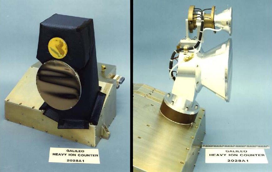
The heavy ion counter that flew on Galileo was a direct sensing instrument. It registered the characteristics of ions in the spacecraft's vicinity that actually entered the instrument.
It did not attempt to form any image of the ions' source. Galileo and Cassini each carried dust detectors. These measured properties, such as mass, species, speed, and direction, of dust particles which actually enter the instrument. They did not attempt to form any image of the source of the dust.
Remote-sensing instruments, on the other hand, exist to form some kind of image or characterization of the source of the phenomena that enter the instrument. In doing so, they record characteristics of objects at a distance, sometimes forming an image by gathering, focusing, and recording light.
A camera, also called an imager, is a classic example of a remote-sensing instrument.
Active and Passive Instruments
Most instruments only receive and process existing light, particles, or other phenomena, and they are said to be passive. Typical of this type would be an imaging instrument viewing a planet that is illuminated by Sunlight, or a magnetometer measuring existing magnetic fields.
An active instrument provides its own means of sensing the remote object. Typical of this would be a radar system. Radar generates pulses of radio waves that it sends to a surface, and then receives their reflections back from the surface, to create images or deduce characteristics of the surface. Some radio science experiments, described in Chapter 8, are also examples of active sensing, since they send radio energy through a planet's atmosphere or rings to actively probe the phenomena, with the results being received directly on Earth.
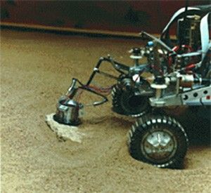
Most of the active-sensing instruments on a spacecraft are also remote-sensing instruments. An exception, an active direct-sensing instrument, would be one that comes in contact with an object of interest while providing a source of energy to probe the object. An example of this type of instrument is the Alpha-Particle X-ray Spectrometer, APXS, carried by the Sojourner Rover on Mars. The instrument contained a source (curium) of alpha-particle radiation (helium nuclei) that the rover placed directly upon various sample rocks on the Martian surface, to determine their composition by acquiring energy spectra of the backscattered alpha particles and x-rays returned from the sample.
Examples of Direct-Sensing Science Instruments
High-energy Particle Detectors
High-energy particle detector instruments measure the energy spectra of trapped energetic electrons, and the energy and composition of atomic nuclei. They may employ several independent solid-state-detector telescopes. The Cosmic Ray Subsystem, CRS, on the Voyagers measures the presence and angular distribution of particles from planets' magnetospheres, and from sources outside our solar system: electrons of 3-110 MeV and nuclei 1-500 MeV from hydrogen to iron. The Energetic Particle Detector (EPD) on Galileo is sensitive to the same nuclei with energies from 20 keV to 10 MeV.
Low-Energy Charged-Particle Detectors
A low-energy charged-particle detector (LECP) is a mid-range instrument designed to characterize the composition, energies, and angular distributions of charged particles in interplanetary space and within planetary systems. One or more solid-state particle detectors may be mounted on a rotating platform.
The Voyagers' LECPs are sensitive from around 10 keV up into the lower ranges of the Cosmic Ray detector. Ulysses' LECP is similar, and is named GLG for its Principal Investigators Gloeckler and Geiss.
Plasma Instruments
Plasma detectors serve the low-end of particle energies. They measure the density, composition, temperature, velocity and three-dimensional distribution of plasmas, which are soups of positive ions and electrons, that exist in interplanetary regions and within planetary magnetospheres.
Plasma detectors are sensitive to solar and planetary plasmas, and they observe the solar wind and its interaction with a planetary system.
The Cassini Plasma Spectrometer Subsystem, CAPS, measured the flux (flow rate or density) of ions as a function of mass per charge, and the flux of ions and electrons as a function of energy per charge and angle of arrival.
Dust Detectors
Dust detectors measure the number, velocity, mass, charge, and flight direction of dust particles striking the instrument.
As an example, Galileo's instrument could register up to 100 particles per second and was sensitive to particle masses of between 10-16 and 10-6 gram.
The Heidelberg Dust Research Group was responsible for dust detection experiments on many spacecraft, including Galileo, Ulysses, Cassini, DUNE, ISO, Rosetta, and Stardust.
Cassini's Cosmic Dust Analyzer, CDA, could determine the species of material in some dust particles as well as the properties mentioned above.
Magnetometers
Magnetometers are direct-sensing instruments that detect and measure the interplanetary and solar magnetic fields in the vicinity of the spacecraft.
They typically can detect the strength of magnetic fields in three planes.
As a magnetometer sweeps an arc through a magnetic field when the spacecraft rotates, an electrical signature is produced proportional to the strength and structure of the field.

The Voyager Magnetometer Experiment (MAG) consists of two low-field magnetometers and two high-field magnetometers that together provide measurement of fields from 0.02 nano-Tesla (nT) to 2,000,000 nT. Voyager magnetometers were built at NASA GSFC where their investigation team resides.
On the spacecraft, the instruments populate a 13-meter-long fiberglass boom to keep them away from on-board interference. The magnetometers provide direct field measurement of both the planetary and the interplanetary media. Having completed their exploration of the outer planets, the Voyager magnetometers are now a key component of the Voyager Interstellar Mission, collecting measurements of magnetic fields far from the Sun.
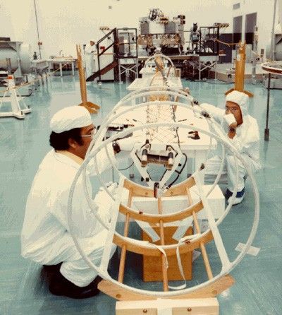
It is typical for magnetometers to be isolated from the spacecraft on long extendable booms. Since such booms cannot support their own weight under the 1-G gravitational acceleration on Earth's surface, a cage arrangement suspends the boom as it extends.
The Cassini spacecraft deployed its magnetometer boom, supporting dual technique magnetometers, during the Earth-flyby period of its mission in 1999.
Plasma Wave Detectors
Plasma wave detectors typically measure the electrostatic and electromagnetic components of plasma waves in three dimensions. The instrument functions like a radio receiver sensitive to the wavelengths of plasma in the solar wind from about 10 Hz to about 60 kHz. When within a planet's magnetosphere, it can be used to detect atmospheric lightning and events when dust particles strike the spacecraft. The Voyagers' plasma wave data has produced sound recordings of the particle hits the spacecraft experienced passing through the ring planes of the outer planets.
Mass Spectrometers
Mass Spectrometers, for example the Cassini Spacecraft's INMS, Ion and Neutral Mass Spectrometer, report the species of atoms or molecules that enter the instrument. Another example is the Huygens' GCMS, Gas Chromatograph Mass Spectrometer, which analyzed the atmosphere of Titan as the probe parachuted toward Titan's surface in 2004. After landing, it also reported on surface composition.
Examples of Remote-Sensing Science Instruments
Planetary Radio Astronomy Instruments
A planetary radio astronomy instrument measures radio signals emitted by a target such as a Jovian planet. The instrument on Voyager is sensitive to signals between about 1 kHz and 40 MHz and uses a dipole antenna 10 m long, which it shares with the plasma wave instrument. The planetary radio astronomy instrument detected emissions from the heliopause in 1993 (see the illustration in Chapter 1). Ulysses carries a similar instrument.
Imaging Instruments
An imaging instrument uses optics such as lenses or mirrors to project an image onto a detector, where it is converted to digital data. Natural color imaging requires taking three exposures of the same target in quick succession through different color filters, typically selected from a filter wheel. Earth-based processing combines data from the three black and white images, reconstructing the original color by utilizing the three values for each picture element (pixel). Movies are produced by taking a series of images over an extended period of time.
In the past, the detector that created the image was a vacuum tube resembling a small CRT (cathode-ray tube), called a vidicon. In a vidicon, signals applied to deflection coils and focus coils sweep an electron beam from a heated cathode (electron source) across a photoconductor coating inside the tybe's glass front where the image is focused. Light striking the photoconductor causes its grains to leak their electric charge in proportion to the light's intensity. The sweeping beam's current would vary as it recharges depleted grains' charges to the point they repel the beam's electrons. This current becomes the basis for the digital video signal produced. Viking, Voyager, and Mariner spacecraft used vidicon-based imaging systems. A vidicon requires a fairly bright image to detect.
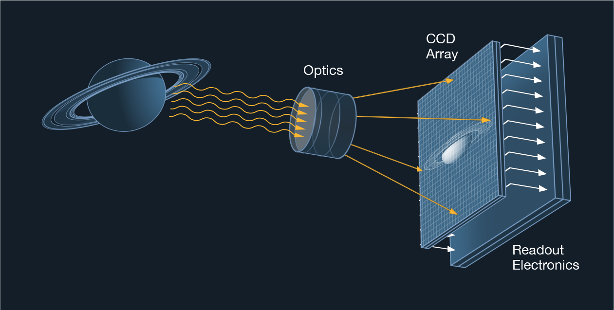
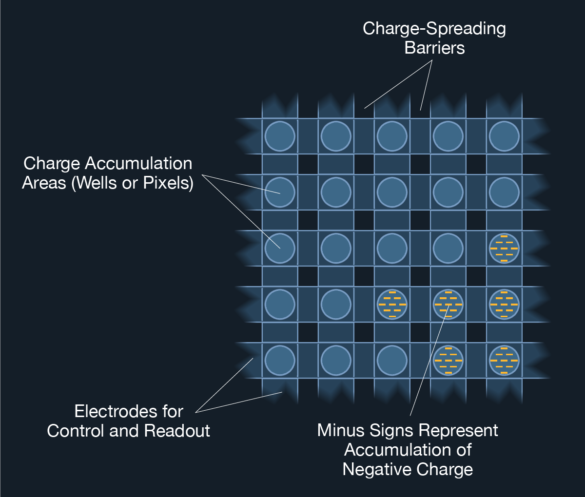
Modern spacecraft use charge-coupled devices (CCD). A CCD is usually a large-scale integrated circuit having a two-dimensional array of hundreds of thousands, or millions, of charge-isolated wells, each representing a pixel. Light falling on a well is absorbed by a photoconductive substrate such as silicon and releases a quantity of electrons proportional to the intensity of light. The CCD detects and stores accumulated electrical charge representing the light level on each well over time. These charges are read out for conversion to digital data. CCDs are much more sensitive to light of a wider spectrum than vidicon tubes, they are less massive, require less energy, and they interface more easily with digital circuitry. It is typical for CCDs to be able to detect single photons.
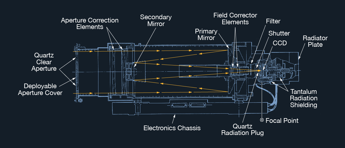
Galileo's Solid State Imaging instrument (SSI), which pioneered the technology, contains a CCD with an 800 x 800 pixel array. The optics for Galileo's SSI, inherited from Voyager, consist of a Cassegrain telescope with a 176.5-mm aperture and a fixed focal ratio of f/8.5. Since the SSI's wavelength range extends from the visible into the near-infrared, the experimenters are able to map variations in the satellites' color and reflectivity that show differences in the composition of surface materials.
Not all CCD imagers have two-dimensional arrays. The HIRISE instrument, or High-Resolution Imaging Science Experiment, on the Mars Reconnaissance Orbiter (MRO) spacecraft has detectors made of single lines of CCD sensors. A two-dimensional image is built up as the image of the Martian surface moves across this one-dimensional detector while the spacecraft moves in orbit, much as a page moves across the detector in a fax machine. HIRISE often achieves a resolution of less than 25cm per pixel. The Mars Orbiter Camera (MOC) on the Mars Global Surveyor spacecraft, also used a single-dimension detector.
The Magnetosphere Imager
Cassini carried a unique instrument that had never been flown before in the outer solar system. The Magnetospheric Imaging Instrument (MIMI) Ion and Neutral Camera (INCA) could form images of the giant magnetic envelopes of Jupiter and its main objective, Saturn, as well as fields associated with Saturn's moons.
MIMI INCA doesn't use CCDs to make images. In fact it doesn't even use light at all. MIMI INCA is more like a particle detector, although unlike most particle detectors, it is actually a remote sensing instrument. MIMI INCA senses ions and neutral atoms that have been flung out of a planet's magnetosphere, forming an image of the source of the particles.
Polarimeters
Polarimeters are optical instruments that measure the direction and extent of the polarization of light reflected from their targets. Polarimeters consist of a telescope fitted with a selection of polarized filters and optical detectors. Careful analysis of polarimeter data can infer information about the composition and mechanical structure of the objects reflecting the light, such as various chemicals and aerosols in atmospheres, rings, and satellite surfaces, since they reflect light with differing polarizations. A polarimeter's function may be integrated with another instrument, such as a camera, or the Voyager photopolarimeter that combines functions with a photometer.
The molecules of crystals of most materials are optically asymmetrical; that is, they have no plane or center of symmetry. Asymmetrical materials have the power to rotate the plane of polarization of plane-polarized light.
Photometers
Photometers are optical instruments that measure the intensity of light from a source. They may be directed at targets such as planets or their satellites to quantify the intensity of the light they reflect, thus measuring the object's reflectivity or albedo. Also, photometers can observe a star while a planet's rings or atmosphere intervene during occultation, thus yielding data on the density and structure of the rings or atmosphere. One of the three instruments on the Spitzer Space Infrared Facility (SIRTF) is a photometer designed to measure the intensity of stars in the infrared.
Spectroscopic Instruments
Spectroscopy (see Chapter 6) provides a wealth of information for analysis of observed targets. The field of spectroscopy includes methods for analysis of virtually every part of the electromagnetic spectrum. Most are differentiated as either atomic or molecular based methods, and they can be classified according to the nature of their interaction:
- Absorption spectroscopy involves observing how substances absorb electromagnetic radiation at certain wavelengths. Signatures of atoms or molecules can be recognized by dips in a spectrum's intensity at specific wavelengths, as light passes through an atmosphere for example.
- Emission spectroscopy involves observing how substances radiate electromagnetic radiation at certain wavelengths. Hot metals, for example, radiate a continuous spectrum of many (or all) wavelengths, while excited gasses emit various discreet wavelengths, giving each specimen a characteristic "fingerprint."
- Scattering spectroscopy measures the amount of light that a substance scatters at certain wavelengths, incident angles, and polarization angles.
Spectroscopic instruments are optical remote-sensing instruments that split the light received from their targets into component wavelengths for measuring and analyzing. In general, a spectroscope provides spectral results visible to the eye, for example through an eyepiece on the instrument. Spectrometers and spectrographs use electronic detectors, such as CCDs, and return data representing the intensity of various parts of the spectrum observed. Instruments on spacecraft typically employ a diffraction grating to disperse the incoming light signal, while a spectroscope might employ either a prism or a grating.
A Compact Disc (CD) or Digital Versatile Disk (DVD) offers an example of a spectroscopic diffraction grating. Observing a bright light shining on the microscopic data tracks on its surface demonstrates the effect diffraction gratings produce, separating light into its various wavelength, or color, components. The apparent separation of wavelengths is due to constructive and destructive interference of light waves reflecting at varying angles from the grating lines according to their wavelengths. A similar effect can be seen from a thin layer of oil floating on water.
Inexpensive "diffraction glasses" provide another effective way to explore spectroscopy at home or in the classroom.
Spectrometers carried on spacecraft are typically sensitive in the infrared, visible, and ultraviolet wavelengths. The Near-Infrared Mapping Spectrometer, NIMS, on Galileo mapped the thermal, compositional and structural nature of its targets using a two-dimensional array of pixels.
An imaging or mapping spectrometer provides spectral measurements for each of the many the pixels of an image the instrument obtains, thus supplying spectral data for many different points on a target body all at once.
Cassini's ultraviolet instrument is the Ultraviolet Imaging Spectrograph, UVIS. Its infrared instrument is the Composite Infrared Mapping Spectrometer, CIRS. Cassini's Visible and Infrared Mapping Spectrometer, VIMS, produce images whose every pixel contains spectral data at many different wavelengths. It is as though the instrument returns a whole stack of images with each observation, one image at each wavelength. Such data units are frequently called "cubes."
Infrared Radiometers
An infrared radiometer is a telescope-based instrument that measures the intensity of infrared (thermal) energy radiated by the targets. One of its many modes of observing is filling the field of view completely with the disc of a planet and measuring its total thermal output. This technique permits the planet's thermal energy balance to be computed, revealing the ratio of solar heating to the planet's internal heating. Another application measures Mars's atmospheric and surface thermal properties.
Other Instruments
Follow the links below for additional instrument descriptions:
Combinations
As mentioned above, sometimes various optical instrumentation functions are combined into a single instrument, such as photometry and polarimetry combined into a photopolarimeter, or spectroscopy and radiometry combined into a radiometer-spectrometer instrument. One example was Galileo's Photopolarimeter Radiometer instrument, PPR. Another example is the Voyagers' infrared interferometer spectrometer and radiometers, IRIS.
Cooling
CCD detectors in imagers and some spectrometry instruments perform best when they are cool. In infrared instruments, cooling essential for maintaining a signal-to-noise ratio that permits useful observations. Fortunately, it is easy to cool some detectors in flight. On Cassini, for example, each of the optical detectors is mounted to a thermally conductive metal part, that thermally connects to a radiator facing deep space. As long as flight operations keeps Sunlight off the radiator, the detector's heat will radiate away into space. Detector temperatures in the neighborhood of 55 K can easily be maintained in this manner.
Observatory spacecraft instruments dedicated to sensing infrared or longer wavelengths need more elaborate cooling. The Hubble Space Telescope's NICMOS (Near Infrared Camera and Multi-Object Spectrometer) originally used solid nitrogen coolant to reduce the detector temperature to 40 K, although it proved to be problematic. The Spitzer Infrared Telescope Facility (SIRTF) achieves a temperature of 1.4 K for its detectors by vapor cooling with helium effluent. BICEP (Background Imaging of Cosmic Extragalactic Polarization), is a ground-based instrument being developed to measure the polarization of the cosmic microwave background from Antarctica. Its detectors are cooled to 250 milli-Kelvens using a helium refrigeration system.
Scan Platforms
Optical instruments are sometimes installed on an articulated, powered appendage to the spacecraft bus called a scan platform, which points in commanded directions, allowing optical observations to be taken independently of the spacecraft's attitude. This is the case on Voyager and Galileo. Most newer spacecraft are designed without scan platforms, since a scan platform adds to a spacecraft's complement of mechanical and other subsystems, increasing mass and potential for failure. The alternative is to mount optical instruments directly to the spacecraft and rotate the entire spacecraft to point them. This approach is feasible due to the availability of large-capacity data storage systems that can record data while the spacecraft is off Earth-point carrying out observations.
Examples of Active Sensing Science Instruments
Synthetic Aperture Radar Imaging
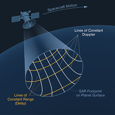
Some solar system objects that are candidates for radar imaging are covered by clouds or haze, making optical imaging difficult or impossible. These atmospheres are transparent to radio frequency waves, and can be imaged using Synthetic Aperture Radar (SAR) which provides its own penetrating illumination with radio waves. SAR is more a technique than a single instrument. It uses hardware and software, as most instruments do, but it also employs the motion of the spacecraft in orbit. SAR synthesizes the angular resolving power of an antenna many times the size of the antenna aperture actually used. SAR illuminates its target to the side of its direction of movement, and travels a distance in orbit while the reflected, phase-shift-coded pulses are returning and being collected. This motion during reception provides the basis for synthesizing an antenna (aperture) on the order of kilometers in size, using extensive computer processing.
For a SAR system to develop the resolution equivalent to optical images, the spacecraft's position and velocity must be known with great precision, and its attitude must be controlled tightly. This levies demands on the spacecraft's attitude control system, and requires spacecraft navigation data to be frequently updated. SAR images are constructed of a matrix where lines of constant distance or range intersect with lines of constant Doppler shift.
Magellan's radar instrument alternated its active operations as a SAR imaging system and radar altimeter with a passive microwave radiometer mode several times per second in orbit at Venus.
Altimeters

A spacecraft's altimeter sends coded radio pulses, or laser-light pulses, straight down to a planet's surface (the nadir) to measure variations in the height of the terrain below. The signals are timed from the instant they leave the instrument until they are reflected back, and the round-trip distance is obtained by dividing by the speed of light, and factoring in known equipment processing delays. Dividing by two then approximates the one-way distance between the instrument and the surface. Actual terrain height is then deduced based upon precise knowledge of the spacecraft's orbit.
The Pioneer 12 spacecraft and the Magellan spacecraft used radar altimeters at Venus. Laser altimeters generally have a smaller footprint, and thus higher spatial resolution, than radar altimeters. They also require less power. The Mars Global Surveyor spacecraft carried a laser altimeter that used a small Cassegrain telescope. Known as MOLA for Mars Orbiter Laser Altimeter, its technology formed the basis for an experiment flown in Earth orbit in 1997 by the Space Shuttle.
Some Links to Spacecraft Science Instrument Pages
Each of these linked pages is a complete list of all of the science instruments on a spacecraft, with links to information about each instrument. Among them you'll find direct- and remote-sensing instruments, and active and passive sensing instruments.
For additional information:
NASA:
- Deep Space 1
- Voyager Science Instruments
- Galileo Science Experiments
- Cassini Science Instruments
- Huygens Science Instruments
- Mars Global Surveyor Science Instruments
- Mars Express Science Instruments
- New Horizons Science Instruments
- Venus Express Science Instruments
- Messenger Science Instruments
- Ulysses Science Instruments
- Mars Exploration Rover (Spirit, Opportunity) Science Instruments
- Mars Pathfinder Science Instruments
- Alpha-Particle X-ray Spectrometer
- CRS (Cosmic Ray Subsystem)
- EPD (Energetic Particles Detector
- Heavy ion counter
- INMS (Ion and Neutral Mass Spectrometer)
- GCMS (Gas Chromatograph Mass Spectrometer)
- Wide angle (Voyager's Wide Angle Camera
- Narrow angle (Voyager's Narrow Angle Camera)
- MRO (Mars Reconnaissance Orbiter
- MIMI (Magnetospheric Imaging Instrument)
- MIMI's view of Jupiter
- MIMI's view of Saturn
- Photopolarimeter
- Photometer