


Chapter 11: Onboard Systems
Page One | Page Two | Page Three | Page Four
Attitude and Articulation Control Subsystems (AACS)
The path a rocket or guided missile takes during powered flight is directly influenced by its attitude, that is its orientation in space. During the atmospheric portion of flight, fins may deflect to steer a missile. Outside the atmosphere, changing the direction of thrust by articulating exhaust nozzles or changing the rocket's attitude influences its flight path. Thus the term guidance and control has become associated with attitude control during the powered ascent phase of a spacecraft's mission. After a few minutes' launch, though, a spacecraft may face a mission of many years in freefall, during which its attitude has no relation to guidance except during short, infrequent propulsive maneuvers.
A spacecraft's attitude must be stabilized and controlled so that its high-gain antenna may be accurately pointed to Earth for communications, so that onboard experiments may accomplish precise pointing for accurate collection and subsequent interpretation of data, so that the heating and cooling effects of Sunlight and shadow may be used intelligently for thermal control, and also for guidance: short propulsive maneuvers must be executed in the right direction.
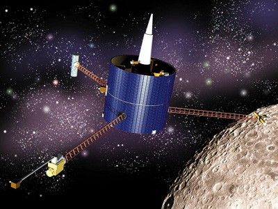
Spin: Stabilization can be accomplished by setting the vehicle spinning, like the Pioneer 10 and 11 spacecraft in the outer solar system, Lunar Prospector, and the Galileo Jupiter orbiter spacecraft, and its atmospheric probe. The gyroscopic action of the rotating spacecraft mass is the stabilizing mechanism. Propulsion system thrusters are fired only occasionally to make desired changes in spin rate, or in the spin-stabilized attitude. In the case of Galileo's Jupiter atmospheric probe, and the Huygens Titan probe, the proper attitude and spin are initially imparted by the mother ship.
3-Axis: Alternatively, a spacecraft may be designed for active three-axis stabilization. One method is to use small propulsion-system thrusters to incessantly nudge the spacecraft back and forth within a deadband of allowed attitude error. Voyagers 1 and 2 have been doing that since 1977, and have used up about three-fourths of their 100 kg of propellant as of December 2012. Thrusters are also referred to as mass-expulsion control systems, MEC, or reaction-control systems, RCS.
Another method for achieving three-axis stabilization is to use electrically-powered reaction wheels, also called momentum wheels. Massive wheels are mounted in three orthogonal axes aboard the spacecraft. They provide a means to trade angular momentum back and forth between spacecraft and wheels. To rotate the vehicle in one direction, you spin up the proper wheel in the opposite direction. To rotate the vehicle back, you slow down the wheel. Excess momentum that builds up in the system due to external torques, caused for example by solar photon pressure or gravity gradient, must be occasionally removed from the system by applying torque to the spacecraft, and allowing the wheels to acquire a desired speed under computer control. This is done during maneuvers called momentum desaturation, (desat), or momentum unload maneuvers. Many spacecraft use a system of thrusters to apply the torque for desats. The Hubble Space Telescope, though, has sensitive optics that could be contaminated by thruster exhaust, so it used magnetic torquers that interact with the Earth's magnetic field during its desat maneuvers.
There are advantages and disadvantages to both spin stabilization and 3-axis stabilization. Spin-stabilized craft provide a continuous sweeping motion that is desirable for fields and particles instruments, as well as some optical scanning instruments, but they may require complicated systems to de-spin antennas or optical instruments that must be pointed at targets for science observations or communications with Earth.
Three-axis controlled craft can point optical instruments and antennas without having to de-spin them, but they may have to carry out special rotating maneuvers to best utilize their fields and particle instruments. If thrusters are used for routine stabilization, optical observations such as imaging must be designed knowing that the spacecraft is always slowly rocking back and forth, and not always exactly predictably. Reaction wheels provide a much steadier spacecraft from which to make observations, but they add mass to the spacecraft, they have a limited mechanical lifetime, and they require frequent momentum desaturation maneuvers, which can perturb navigation solutions because of accelerations imparted by their use of thrusters.
No matter what choices have been made — spin or 3-axis stabilization, thrusters or reaction wheels, or any combinations of these — the task of attitude and articulation control falls to an AACS computer running highly evolved, sophisticated software.

Articulation: Many spacecraft have components that require articulation. Voyager and Galileo, for example, were designed with scan platforms for pointing optical instruments at their targets largely independently of spacecraft orientation. Many spacecraft, such as Mars orbiters, have solar panels which must track the Sun so they can provide electrical power to the spacecraft. Cassini's main engine nozzles are steerable. Knowing where to point a solar panel, or scan platform, or a nozzle — that is, how to articulate it — requires knowledge of the spacecraft's attitude. Since AACS keeps track of the spacecraft's attitude, the Sun's location, and Earth's location, it can compute the proper direction to point the appendages. It logically falls to one subsystem, then, to manage both attitude and articulation. The name AACS may even be carried over to a spacecraft even if it has no appendages to articulate.
Celestial Reference: Which way is "up"? Many different devices may be chosen to provide attitude reference by observing celestial bodies. There are star trackers, star scanners, solar trackers, Sun sensors, and planetary limb sensors and trackers. Many of today's celestial reference devices have a great deal of intelligence, for example automated recognition of observed objects based on built-in star catalogs. Voyager's AACS takes input from a Sun sensor for yaw and pitch reference. Its roll reference comes from a star tracker trained continuously on a single bright star (Canopus) at right angles to Sunpoint. Galileo took its references from a star scanner which rotated with the spinning part of the spacecraft, and a Sun sensor was available for use in maneuvers. Magellan used a star scanner to take a fix on two bright stars during a special maneuver once every orbit or two, and its solar panels each held a Sun sensor.
Inertial Reference: Celestial references are not always available or appropriate. Gyroscopes of some kind are typically carried as inertial reference devices to provide attitude reference signals to AACS for those periods when celestial references are not being used. For Magellan, this was the case nearly continuously; celestial references were used only during specific star scan maneuvers once every orbit or two. Other spacecraft, such as Galileo, Voyager and Cassini, were designed to use celestial reference nearly continuously, and they rely on inertial reference devices for their attitude reference only during relatively short maneuvers when celestial reference is lost.
In either case, gyro data must be taken with a grain of salt; mechanical gyroscopes precess and drift due to internal friction. Non-mechanical "gyros" also drift due to design constraints. Their rates of drift are carefully calibrated, so that AACS may compensate as best it can, when it computes its attitude knowledge using gyro references. (Note that the word "gyro" is commonly used as shorthand for "inertial reference unit," even though some units do not employ the gyroscopic effect at all.)
Don't Confuse Gyros and Reaction Wheels.
Gyros provide inertial reference inputs to AACS computers. If they have any moving parts, they are small and lightweight.
Reaction wheel are fairly massive attitude control devices at the output of AACS computers.
A few different inertial reference technologies are in use on today's spacecraft. The newer technologies depart from employing the mechanical gyroscopic effect, in favor of different physical principles:
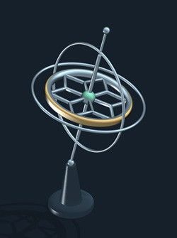
- Mechanical gyros Used on Voyager and Magellan, these rely on the rigidity in space of the axis of a spinning mass to provide attitude reference signals. This effect is easily demonstrated in a toy gyroscope. Mechanical gyros have limited lifespans due to mechanical wear.
- Laser ring gyros and fiber-optic laser gyros These use interferometry to sense the Doppler effect induced in beams of light, when the unit is rotated. Laser gyros have no moving parts to wear out.
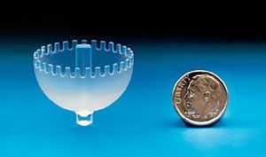
- Hemispherical resonator gyros
Used on NEAR and Cassini, these sense movement of a standing mechanical wave in a fused-silica shell. The wave is not unlike a wineglass 'singing' as you slide your finger around the rim. Null points in the wave precess when the unit is rotated. Other than their vibrating sensor shells, hemispherical resonator gyros have no moving parts.
Telecommunications Subsystems
This section deals specifically with telecommunications equipment on board a spacecraft.
A broader view of telecommunications issues may be found in Chapter 10, and the Deep Space Network's role is detailed in Chapter 18.
Telecommunications subsystem components are chosen for a particular spacecraft in response to the requirements of the mission profile. Anticipated maximum distances, planned frequency bands, desired data rates, available on-board electrical power (especially for a transmitter), and mass limitations, are all taken into account.
Each of the components of this subsystem is discussed below:
High-Gain Antennas (HGA)
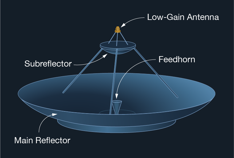
Dish-shaped HGAs are the spacecraft antennas principally used for long-range communications with Earth. The amount of gain achieved by an antenna (indicated here as high, low, or medium) refers to the relative amount of incoming radio power it can collect and focus into the spacecraft's receiving subsystems from Earth, and outbound from the spacecraft's transmitter. In the frequency ranges used by spacecraft, this means that HGAs incorporate large paraboloidal reflectors. The cassegrain arrangement, described in Chapter 6, is the HGA configuration used most frequently aboard interplanetary spacecraft. Ulysses, which uses a prime focus feed, is one exception.
HGAs may be either steerable or fixed to the spacecraft bus. The Magellan HGA, which also served as a radar antenna for mapping and as a drogue for aerobraking, was not articulated; the whole spacecraft had to be maneuvered to point the HGA to Earth for communications.
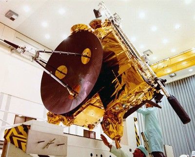
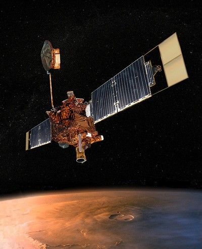
The Mars Global Surveyor spacecraft's HGA was on an articulated arm to allow the antenna to remain on Earth-point, independent of the spacecraft's attitude while it mapped the surface of Mars. Galileo's HGA was designed to unfold like an umbrella after launch to enable the use of a larger diameter antenna than would have fit in the Space Shuttle cargo bay if a fixed antenna had been chosen. It did not unfurl, though, and Galileo had to carry out its mission using a low-gain antenna constrained to low data rates.
The larger the collecting area of an HGA, the higher the possible gain, and the higher the data rate it can support. The higher the gain, the more highly directional it is (within limits of frequency band in use). An HGA on an interplanetary spacecraft must be pointed to within a fraction of a degree of Earth for communications to be feasible. Once this is achieved, communications take place over the highly focused radio signal. This is analogous to using a telescope, which provides magnification (gain) of a weak light source, but requires accurate pointing.
To continue the telescope analogy, no magnification is achieved with the unaided eye, but it covers a very wide field of view, and need not be pointed with great accuracy to detect a source of light, as long as it is bright enough. In case AACS fails to be able to point a spacecraft's HGA with high accuracy for one reason or another, there must be some other means of communicating with the spacecraft.
An HGA can serve additional purposes unrelated to telecommunications. It can be a Sunshade. Magellan's and Cassini's are good examples. They produced shade for the rest of the spacecraft when pointed to the Sun. Cassini's HGA also served to protect the rest of the spacecraft from the thousands of micrometeoroid impacts it endured crossing Saturn's ring plane during Saturn Orbit Insertion.
Low-gain antennas (LGAs) provide wide-angle coverage (the "unaided-eye," in the analogy) at the expense of gain. Coverage is nearly omnidirectional, except for areas which may be shadowed by the spacecraft body. LGAs are designed to be useable for relatively low data rates, as long as the spacecraft is within relatively close range, several AU for example, and the DSN transmitter is powerful enough. Magellan could use its LGA at Venus's distance, but Voyager must depend on its HGA since it is over 90 AU away.
Some LGAs are conveniently mounted atop the HGA's subreflector, as in the diagram of the HGA. This was the case with Voyager, Magellan, Cassini, and Galileo. Ulysses carries an LGA atop its prime focus feed. A second LGA, designated LGA-2, was added to the Galileo spacecraft in the mission redesign which included an inner-solar system gravity assist. LGA-2 faced aft, providing Galileo with nearly full omnidirectional coverage by accommodating LGA-1's blind spots. Cassini's LGA-2 also is mounted near the aft end of the spacecraft, so it can provide coverage when LGA-1 is shaded by the spacecraft body.
MGAs are a compromise, providing more gain than an LGA, with wider angles of pointing coverage than an HGA, on the order of 20 or 30 degrees. Magellan carried an MGA consisting of a large cone-shaped feed horn, which was used during some maneuvers when the HGA was off Earth-point.
A spacecraft transmitter is a lightweight electronic device that generates a tone at a single designated radio frequency, typically in the S-band, X-band, or Ka-band for communications and radio science. This tone is called the carrier. As described in Chapter 10, the carrier can be sent from the spacecraft to Earth as a pure tone, or it can be modulated with data or a data-carrying subcarrier.
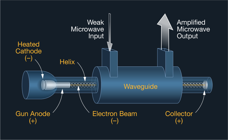
The signal generated by the spacecraft transmitter is passed to a power amplifier, where its power is boosted to the neighborhood of tens of watts. This microwave-band power amplifier may be a solid state amplifier (SSA) or a traveling wave tube (TWT, also TWTA, pronounced "tweeta," for TWT Amplifier).
A TWTA is a vacuum tube. It uses the interaction between the field of a wave propagated along a waveguide, and a beam of electrons traveling along with the wave. The electrons tend to travel slightly faster than the wave, and on the average are slowed slightly by the wave. The effect amplifies the wave's total energy. TWTAs require a regulated source of high voltage.
The output of the power amplifier is ducted through waveguides and commandable waveguide switches to the antenna of choice: HGA, MGA, or LGA.
Commandable waveguide switches are also used to connect the antenna of choice to a receiver. The receiver is an electronic device which is sensitive to a narrow band of radio frequencies, generally plus and minus a few kHz of a single frequency selected during mission design. Once an uplink is detected within its bandwidth, the receiver's phase-lock-loop circuitry (PLL) will follow any changes in the uplink's frequency within its bandwidth. JPL invented PLL technology in the early 1960s, and it has since become standard throughout the telecommunications industry.
The receiver's circuitry can provide the transmitter with a frequency reference coherent with the received uplink. This means the downlink signal's phase bears a constant relation to that of the uplink signal. The received uplink, once detected, locked onto, and stepped down in frequency, is stripped of its command-data-carrying subcarrier, which is passed to circuitry called a command detector unit (CDU). The CDU converts the analog phase-shifts that were modulated onto the uplink, into binary 1s and 0s, which are then typically passed to the spacecraft's Command and Data Subsystem (CDS) or equivalent.
Usually, transmitters and receivers are combined into a single electronic device on a spacecraft, which is called a transponder.
Note that in everyday terrestrial use, a transmitter-receiver not designed to generate a coherent signal is called a transceiver.
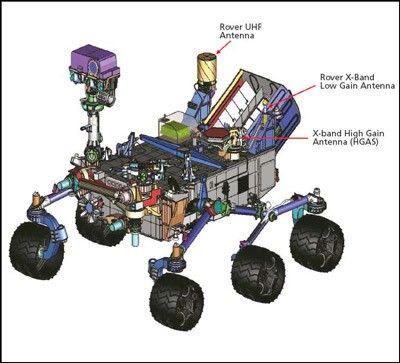
Communications Relay
Mars orbiting spacecraft are equipped with a UHF antenna and receiver, to serve as a relay from spacecraft on the surface.
The Mars Exploration Rovers Spirit and Opportunity, for example, routinely transmit their data in the UHF radio frequency band, as Mars Global Surveyor (MGS) passed overhead in Mars orbit.
MGS stored the data on board, and then transmitted it back to Earth on its X-band communications link.
The same service is also provided by orbiters Mars Odyssey and Mars Express. There's more about relay operations in Chapter 17.