Chapter 10: Telecom
Chapter Objectives
Upon completion of this chapter you will be aware of the major factors involved in communicating across interplanetary distances, including uplink, downlink, coherence, modulation, coding, and multiplexing. You will also be aware that additional coverage of this subject appears in different chapters.
This chapter offers a broad view into some basic telecommunications issues, including both spacecraft and Earth-based components. Chapter 18 builds on the Deep Space Network's role in telecommunications, and more details of onboard spacecraft telecommunications equipment appear under Telecommunications Subsystems in Chapter 11.
Transmitters and Receivers
Chapter 6 showed that electromagnetic waves propagate any time there is a change in an electric current. Also, electromagnetic waves induce electric currents in conductors they encounter.
This is the basis for radio communications. A radio transmitter, then, creates a changing electric current, allowing the resulting waves to propagate. A radio receiver picks up either the electric component or the magnetic component of the electromagnetic signal depending on its antenna design, which is then amplified for further use."
Since the wires in a house carry electric current that changes typically at the rate of 60 Hz (in the U.S., 50 Hz in some other locations), it is easy to pick up a small induced 60 Hz current in any free conductor anywhere in the house. Try it: a sensitive earphone or an amplifier reveals an audible 60-Hz hum, unless its input is carefully shielded.
Practical radio transmitters and receivers operate on the same basis, but at much higher frequencies than 60 Hz. With frequencies in the microwave region of the spectrum and higher, electromagnetic energy can easily be confined to a narrow beam, like a beam of light.
Signal Power
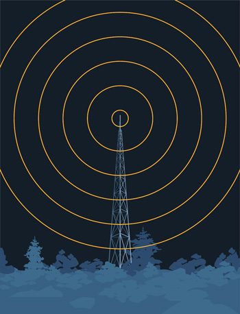
The KPFK FM radio broadcast transmitter on Mt. Wilson near Los Angeles has a power of 112 kW and a frequency of 90.7 MHz. The transmitter is no more than 15 km away from JPL. Your automobile radio receiver has a simple antenna to pick up the induced signal.
By comparison, a spacecraft's transmitter might have no more than 20 W of radiating power, but it can bridge distances measured in tens of billions of kilometers. How can that be? One part of the solution is to employ microwave frequencies and use reflectors to concentrate all available power into a narrow beam, instead of broadcasting it in all directions. A spacecraft typically does this using a Cassegrain dish antenna, perhaps a few meters in diameter, trained precisely toward Earth.
The use of a cassegrain high-gain antenna (HGA) can increase telecommunications performance substantially. Consider a radio transmitter that radiates from a single point evenly in all directions. This theoretical concept (it cannot actually exist) is called an isotropic radiator. Voyager's, HGA, for example, provides a gain of 47 dBi at X-band. The reference "i" in dBi means the ratio is referenced to an isotropic radiator. The value of 47 dB (decibels) is 1047/10, which is a factor of more than 50,000. A 20-Watt transmitter using a 47-dBi gain HGA would have an effective power of a megawatt along the highly directional beam. This effective power is called ite Equivalent Isotropically Radiated Power (EIRP).
Another component to the success of interplanetary communications is the fact that there are no significant sources of noise in interplanetary space at the spacecraft's specific frequency. The spacecraft is the only thing that can be detected at that frequency (unless it is happens to be close to the noisy Sun as seen in the sky).
The remainder of the solution is provided by the Deep Space Network's large aperture Cassegrain reflectors (the largest of which offer 74 dBi gain at X-band), cryogenically-cooled low-noise amplifiers, sophisticated receivers, and data coding and error-correction schemes. These systems can collect, detect, lock onto, and amplify a vanishingly small signal that reaches Earth from the spacecraft, and can extract data from the signal virtually without errors.
Uplink and Downlink
The radio signal transmitted from Earth to a spacecraft is known as uplink. The transmission from spacecraft to Earth is downlink. Uplink or downlink may consist of a pure RF tone, called a carrier. Such a pure carrier is useful in many ways, including radio science experiments. On the other hand, carriers may be modulated to carry information in each direction (modulation is detailed later in this chapter).
Commands may be transmitted to a spacecraft by modulating the uplink carrier. Telemetry containing science and engineering data may be transmitted to Earth by modulating the downlink carrier.
Phase Lock
When your FM receiver tunes in a broadcast station, it locks onto the signal using an internal circuit called a phase-locked loop, or PLL. (The PLL combines a voltage-controlled oscillator and a phase comparator designed so the oscillator tracks the phase of an incoming signal.) An oscillator is an electronic circuit that generates a time-varying voltage. PLLs are used in spacecraft and DSN telecommunications receivers, and so it is common to speak of a spacecraft's receiver "locked" onto an uplink, and a DSN receiver "locked" onto a downlink. (Telemetry systems are said to achieve "lock" on data, as described later, but the concept is completely different from a receiver's phase-locked loop.)
One-way, Two-way, Three-way
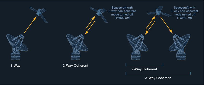
When you're only receiving a downlink from a spacecraft, the communication is called one-way. When you're sending an uplink that the spacecraft is receiving at the same time a downlink is being received at Earth, the communications mode is called two-way.
There are finer points. The communications mode is still called one-way even when an uplink is being received by the spacecraft, but the full round-trip light time hasn't yet elapsed. Picture it this way: You're getting downlink and watching telemetry that shows the state of the spacecraft's own receiver. As long as you see that the spacecraft's receiver is not receiving the uplink, you're one-way. Once you see that the spacecraft's receiver has locked onto the uplink, you're two-way.
Three-way is when you're receiving a downlink on one station, but a different station is providing the uplink. Again, RTLT must have elapsed since the other station's uplink began. If you're watching telemetry from the spacecraft coming in over a DSN station in Australia, and you see the spacecraft's receiver is still in lock on the uplink provided by a DSN station at Goldstone, California, you're three-way.
Coherence
Aside from the information modulated on the downlink as telemetry, the carrier itself is used for tracking and navigating the spacecraft, as well as for carrying out some types of science experiments such as radio science or gravity field mapping. For each of these uses, an extremely stable downlink frequency is required, so that Doppler shifts on the order of fractions of a Hertz may be detected out of many GHz, over periods of many hours. But it would be impossible for any spacecraft to carry the massive equipment required to maintain such frequency stability. Spacecraft transmitters are subject to wide temperature changes, which cause their output frequency to drift.
The solution is to have the spacecraft generate a downlink that is coherent to the uplink it receives.
Down in the basement of each DSN complex, there looms a hydrogen-maser-based frequency standard in an environmentally controlled room, sustained by an uninterruptable power supply. This maser is used as a reference for generating an extremely stable uplink frequency for the spacecraft to use, in turn, to generate its coherent downlink. (It also supplies a signal to the master clock that counts cycles and distributes UTC time.) Its stability is equivalent to the gain or loss of 1 second in 30 million years.
Once the spacecraft receives the stable uplink frequency, it multiplies that frequency by a predetermined constant, and uses that value to generate its downlink frequency. This way, the downlink enjoys all the extraordinarily high stability in frequency that belongs to the massive, sensitive equipment that generated the uplink. It can thus be used for precisely tracking the spacecraft and for carrying out precision science experiments.
The reason a spacecraft's transponder multiplies the received frequency by a constant, is so the downlink it generates won't cause interference with the uplink being received. Cassini's X-band transponder, for example, uses the constant 1.1748999.
The spacecraft also carries a low-mass oscillator to use as a reference in generating its downlink for periods when an uplink is not available, sometimes called an auxiliary oscillator. It is not highly stable, since its output frequency is affected by temperature variations and other conditions.
Ultra-Stable Oscillator
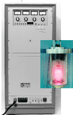
Some spacecraft carry an Ultra-Stable Oscillator (USO), which is kept under tight temperature control (at the expense of added power consumption and mass). The USO is discussed further in Chapter 16. But even the USO has nowhere near the stability of a coherent link.
Because of the stringent frequency requirements for spacecraft operations, JPL stays at the forefront of frequency and timing standards technology. Advances are being undertaken that may replace the hydrogen-maser-based system early in the 21st century.
Data Glitch Going Two-way
Consider a DSN station in lock with a spacecraft's one-way downlink. Now have that station send an uplink. When the spacecraft locks onto the uplink, it abandons the internal frequency reference it was using to generate its downlink. Now it uses the uplink to generate a new downlink frequency. That new downlink frequency will be a lot more stable, but it will likely be a slightly different frequency than the one it was generating on its own.
So when the new coherent downlink reaches the DSN station a round-trip light time after the DSN's transmitter goes on, the station's receiver drops lock on the old downlink, because it isn't there at the same frequency anymore. The DSN receiver has to change frequency, and lock on the new and different downlink frequency. Of course when the DSN receiver goes out of lock, the telemetry system also loses lock and the data stream stops.
It's as if you're tuned in to the KPFK-FM radio broadcast at 90.700 MHz, and suddenly it decides to change to 90.750 MHz. You have to tune your radio to the new frequency, so you're going to miss some of that fascinating Pacifica Radio interview you were following!
The DSN station knows the exact time a coherent downlink will arrive, and will waste no time looking for the new frequency. It may be common, however, to experience a minute with no data while the lockup proceeds, so it is wise to plan for this outage in the early stages of determining what the content of the downlink will be. You don't want to sequence your spacecraft to be downlinking something important at the time it changes to 2-way coherent.
In order to avoid this data glitch when going from two-way coherent to three-way coherent, the two DSN stations coordinate closely to provide an uplink handover.
Picture a spacecraft setting at the western horizon as seen from the Goldstone DSN station. At the same time, the spacecraft is rising on the eastern horizon as seen from the Australian station. At a predetermined time, the Australian station turns on its transmitter, already tuned so it appears to the spacecraft as the same frequency as the uplink it is already receiving (taking into consideration the Doppler shifts induced as the turning Earth moves Australia towards, and Goldstone away from the spacecraft). Then, two seconds later, the Goldstone station turns off its transmitter. Nominally, the spacecraft will not lose lock on the uplink, and so its coherent downlink will not undergo any change in frequency. Telemetry and tracking data continue uninterrupted!
T. W. N. C. On
Most interplanetary spacecraft may also invoke a mode that does not use the uplink frequency as a reference for generating downlink (even if an uplink is present). When invoked, the spacecraft instead uses its onboard oscillator as a reference for generating its downlink frequency. This mode is known as Two-Way Non-Coherent (TWNC, pronounced "twink"). TWNC's default state is typically off, to enjoy the advantages of a coherent link.
When TWNC is on, the downlink is always non-coherent, even if the spacecraft sees an uplink.
Why have a two-way non-coherent capability? Mostly for short-duration Radio Science (RS) experiments. While RS usually needs the most stable coherent downlink available
(referenced to extremely stable ground equipment with TWNC off), they can't always have one. Atmospheric occultation experiments provide an example. When a spacecraft goes behind a planet's atmosphere, the atmosphere corrupts the uplink before it reaches the spacecraft, adding to noise in the downlink. The solution is to turn coherency off (TWNC on, a double-negative phrase), and reference a known and well calibrated spacecraft-generated downlink, as a second-best source. Regularly scheduled non-coherent periods during cruise provide calibration data in support of non-coherent RS experiments.
Recall "two-way" and "three-way" mean there is an uplink and there is a downlink. These terms don't indicate whether the spacecraft's downlink is coherent to a station's uplink.
In common usage, some operations people often say "two-way" to mean "coherent." This is unfortunate. It can lead to confusion. Correctly stated, a spacecraft's downlink is coherent when it is two-way or three-way with TWNC off.
With TWNC on, you can be two-way or three-way and non-coherent.
Modulation and Demodulation, Carrier and Subcarrier
To modulate means to modify or temper in some way. For example, consider a pure-tone carrier of, say, 3 GHz. If you were to quickly turn this tone off and on at the rate of a thousand times a second, we could say you are modulating the carrier with a frequency of 1 kHz using on-off keying.
Spacecraft and DSN carrier signals are modulated not by on-off keying as in the above example, but by shifting the waveform's phase slightly at a carefully clocked rate. This is phase modulation. You can phase-modulate the carrier directly with data. Another scheme is to phase-modulate the carrier with a constant frequency called a subcarrier which in turn carries the data symbols.
In the on-off keying example, we could really call the 1-kHz modulation a subcarrier, in an attempt to simplify the explanation. Now, to stretch the example a bit, you might decide to place data onto this 1-kHz "subcarrier" by varying the timing of some of the on-off transitions.
The same kind of schemes that put data on the downlink are also used on the uplink to carry commands or ranging tones for navigation. Ranging and other navigation topics appear in Chapter 13.
To illustrate the subcarrier scheme, let's say Cassini's X-band downlink carrier is 8.4 GHz. That's pretty close. Cassini's transmitter can impose a modulation of 360 kHz onto that carrier to create a subcarrier. Then, the data can be modulated onto the 360 kHz subcarrier by shifting its phase. In practice, Cassini can modulate data directly onto its carrier, or put it into either a 360 kHz subcarrier or a 22.5 kHz subcarrier. Which scheme is selected depends on the data rates to be used and other factors.
MI=51.6° | The amount of phase shift used to modulate a carrier (or a subcarrier) is called modulation index (or mod index, MI). MI is measured in degrees or radians (see the illustration in Chapter 6). The greater the mod index, the "louder" the modulation. Various MI values are used for different conditions. |
Demodulation is the reverse. It's the process of capturing data symbols from the carrier or subcarrier. It involves detecting the individual phase shifts in the carrier and subcarrier if present, and decoding them into digital data for further processing. The same processes of modulation and demodulation are used commonly with Earth-based computer systems and fax machines transmitting data back and forth over a telephone line. They use a modem, short for modulator / demodulator. Computer and fax modems modulate that familiar audio frequency carrier (you've heard it, it sounds like "beeeeeee, diddle-diddle-diddle") because the telephone system can readily handle it.
Modulation can be seen as power sharing. If there is no modulation, all the power is in the carrier. As you increase modulation, you put more power in the data and less in the carrier but it always adds up to the same amount of power. You decrease carrier power when you add modulation for telemetry, and decrease it again when you add modulation for ranging. When operating near the limits of reception, it may be necessary to choose between telemetry modulation and ranging modulation to preserve a useable downlink, and to choose between ranging modulation and command modulation to preserve a useable uplink.
Beacons
As part of its new technology, the Deep Space 1 spacecraft has demonstrated beacon monitor operations, a mode which may become more widespread as spacecraft intelligence and capabilities increase.
In beacon monitor operations, an on-board data summarization system determines the overall spacecraft health. Then it selects one of 4 subcarrier tones to place on its downlink carrier to indicate whether, or how urgently, it needs contact using the Deep Space Network's larger antennas. These subcarrier tones are quickly and easily detected with low cost receivers and small antennas, so monitoring a spacecraft that uses this technology can free up precious resources of the Deep Space Network.
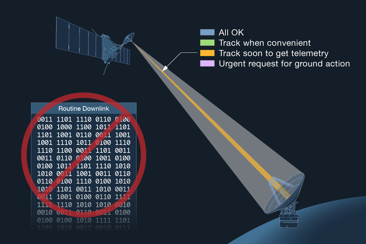
Each beacon tone is like a single note on a musical instrument. One tone might mean that the spacecraft is fine, and it does not need contact with human operators. Another might mean that contact is needed sometime within a month, while a third could mean that contact should be established within a week so that data can be downlinked. Another tone could mean "red alert," indicating the spacecraft needs immediate contact because of some problem.
Symbols and Bits and Coding
Generally, modern spacecraft don't place data bits, as such, onto the carrier or subcarrier. They put symbols there instead. A symbol is a wiggle (or a non-wiggle) in the phase of the carrier or subcarrier. A number of symbols make up a bit. How many depends on the coding scheme being used. Coding is a theoretical field using logic and mathematics to help ensure error-free data transmission. One coding scheme most interplanetary spacecraft use is a forward error correction (FEC) scheme called convolutional coding with Viterbi decoding. Another kind is Reed-Solomon, the same coding your CD player uses to ensure error-free music. Reed-Solomon coding adds bits, but it doesn't affect the ratio of symbols to bits; it's generally imposed prior to the convolutional code. The flavor of convolutional coding that Cassini often uses (k=15, r=1/6) places six symbols on the downlink (carrier or subcarrier) for every bit of data. Thus Cassini's downlink data rate of 82,950 bps requires a symbol rate of 497,700 symbols per second. A recent advance in coding called turbo code is being used on some new missions.
About those phase wigglings... Two schemes are commonly in use for putting them on the downlink or uplink:
- Bi-phase, or Bi-Ø, is the format normally used for putting data directly on a carrier. In this scheme, the phase has to shift from one offset to another, across the zero point, to represent a symbol. The timing of the shift in relation to a symbol time (clock) determines whether the symbol is a "1" or a "0." This scheme is also called Manchester coding.
- NRZ or non-return-to-zero, is the format normally used for putting data onto a subcarrier. In this scheme, a phase deviation is held for the duration of a symbol time (clock) to represent a logical "1." To represent a logical "0," the opposite phase deviation is held for a symbol time. If the symbols are "1110," the first shift is held for three symbol times without returning to zero.
In either case, a number of symbols must be received before a data bit can be recognized, the number depending on what convolutional coding parameters are in use.
Multiplexing
The subjects that follow are more properly described as issues of telemetry, rather than issues of basic telecommunications, which have been the focus until now.
Not every subsystem aboard a spacecraft can transmit its data at the same time, so the data is multiplexed. Cassini has over 13,000 different measurements such as pressures, temperatures, computer states, microswitch positions, science data streams, and so on. To ensure that all necessary data is received, and that important measurements are received more frequently than less important ones, spacecraft are designed to use one of two different multiplexing schemes, described below. Both methods make use of a data structure called a frame. The spacecraft puts a known bit pattern into the data stream to separate the stream into frames. This bit pattern is called a PN (Pseudo-Noise) code, or a sync marker. The ground system searches for this pattern, and identifies all data in between instances of this pattern as a frame. The two multiplexing methods differ in how the spacecraft organizes the bits within the frames, between the sync markers:
- In TDM, or Time Division Multiplexed data, each measurement is commutated (picked up and selectively placed) into a known location in the frame. In a simplified example, it might be agreed that right after the PN code is sent, the imaging system sends 1024 bits of its data, then the propulsion system sends 512 bits, and then the radar system sends 2048 bits. Next comes the PN code marking the start of a new frame. On the ground you'd filter through the data till you recognize the PN code, then start counting bits so you can decommutate or separate out the data. The first 1024 bits are imaging, the next 512 bits are propulsion, and so on. However, this arrangement means that, for instance, radar always gets the same number of bits, even if the instrument has no data to transmit, which can be wasteful.
- Rather than TDM, newer spacecraft use packetizing on both uplink and downlink in accordance with The Consultative Committee for Space Data Systems (CCSDS). In the packetizing scheme for downlink, a burst of data called a packet comes from one instrument or subsystem, followed by a packet from another, and so on, in no specific order. The packets (and partial packets) are packed into the frame tightly, regardless of where each packet starts. Each packet carries an identification of the measurements it contains, the packet's size, etc., so the ground data system can recognize it and handle it properly. Data within a packet normally contains many different commutated measurements from the subsystem or instrument sending the packet. The spacecraft gathers packets (or perhaps parts of packets, depending on their sizes) into frames for downlink, marked with PN code as described above. Packetizing schemes adhere to the International Standards Organization (ISO)'s Open Systems Interconnection (OSI) protocol suite, which recommends how computers of various makes and models can communicate. The ISO OSI is distance independent, and holds for spacecraft light-hours away as well as between workstations in the same office.
Demultiplexing is done at the frame level for TDM, and at the packet level for packet data. In both TDM and packets, the data carries a numeric key to determine which of several predetermined sets of measurements is present. On the ground, the key determines which decom map (decommutation map) will be used to separate out each measurement into its "channel" described below.
Telemetry Lock
Once a DSN receiver has locked onto a downlink, symbols are decoded into bits, and the bits go to a telemetry system. Once the telemetry system recognizes frames reliably, it is said to be in "lock" on the data. The data flow is discussed further in Chapter 18; the intent here is to highlight the difference between receiver lock and telemetry lock.
Channelization
Once all the measurements are identified in the ground system, they are typically displayed as channels. For example,
- Channel T-1234 always shows the temperature of the hydrazine tank.
- Channel A-1234 always shows the speed of reaction wheel number three.
- Channel E-1234 always shows the main bus voltage.
- Channel C-1234 always shows the state of the command decoder.
- Channel P-1234 always shows the pressure in the oxidizer tank. And so on.
These are hypothetical channel identifications, of course. Each spacecraft identifies them differently and may have thousands of different measurements. But the value of each specific measurement will always appear in the same place, in its associated channel. This scheme makes it possible to arrange sets of related data within separate windows on your computer screen. Some data is typically not assigned channels at all, but delivered "raw" instead. Such raw data may include imaging data streams or data from other science instruments.
In addition to telemetry measurements from the spacecraft, monitor data is available from the Deep Space Network to show the performance of its various subsystems, for example antenna elevation or receiver lock status. Monitor channels are typically identified with the letter M, such as Channel M-1234.

